Did anyone mention that animating is really, really hard? Rigging a character in Blender is pretty straight-forward, even if you do it yourself. With just a few mouse clicks, you can easily Rigify a character, and have full IK/FK support. Moving limbs and waving arms around is pretty simple stuff.
But creating a realistic animation - making the character look like a real, living, breathing thing, rather than a stiff, robotic puppet - is really hard. Plus, for some poses, FK (forward kinematics) is ideal. But for some poses, IK is preferable. And getting Blender to play nicely, as you switch from one to the other, is a bit of a nightmare.
Luckily, there's a (relatively) easy solution: BVH.
And ever since the first Microsoft Kinect (originally for XBox) hit the market, indie game developers have had access to a nice, easy, cheap(ish) motion capture device.
The Kinect For Windows package is now discontinued, but you can still use a Kinect One for XBox and a PC connection cable to get the same result.
The cable costs more than the Kinect (though both can be bought online for around £40 if you look carefully). So, of course, we snagged a few and looked at how we can use them for our animations.
While we're waiting for them to arrive, we took a look at BVH animation in Blender. There are quite a few software packages that work with the Kinect One to create BVH animations (we'll try a few out when the hardware actually arrives) - so in the meantime, we thought it best to look at how to use BVH files with our rigged character in Blender.
It turns out, it's actually quite easy to import BVH animations into Blender - simply download the MakeHuman Blender tools, and activate the MakeWalk plug-in in your Blender project.
Then load your character, complete with rig (either a hand-carved rig or a Rigify generated one) and when in pose mode the MakeWalk tab should appear in the Tools panel on the left of the screen (assuming a default pane layout in Blender)
Hit the "load and retarget" button and hey presto! Your character takes on the BVH animation.
If your character stubbornly remains in the t-pose position, use the play/frame advance tools to move through each frame of the animation. If there are no frames of animation in the timeline, check your console for import errors.
Now that was easy. But it's not the end of things. Most BVH files are massively wasteful. They key just about every bone, location and rotation on just about every frame. And there are also a couple of frames where "glitchy" poses appear.
Even for an energetic ballet dance move, something doesn't look quite right in this frame!
So there's a bit of tidying up to do. But, in general, it's a quick and easy way to get a basic animation into Blender. We usually just flick through the animation and where any one frame looks particularly out of place, simply remove that keyframe. As long as there is a decent keyframe before and after the offending frame (or frames, you can get away with deleting up to 5-10 consecutive frames before it's noticable) you should be ok. Looking at the dope sheet however, shows us a slightly different story:
Wow! That's a lot of keyframe information.
Probably about 90% of this keyframe information is unnecessary (that's just a guess - plucked a number completely out of thin air). But given that Blender (and, eventually, our target platform Unity) will automatically tween between two poses, what we really need to do is grab just the pertinent frames of action - keep the main key poses between actions, and let Blender fill in the gaps, rather than force our model into a set pose on every single frame.
With our animation, we found that the first 21 frames were basically the same pose - the actor in the BVH mo-cap studio obviously readying themselves to perform the action. So we kept frame one and frame 22 and deleted all the other frames between these two. The animation played more or less the same, but with only one key pose, instead of 22, at the start of the animation.
Here's the same dope sheet, but with only the important frames kept in - any frames where the character was simply transitioning from one pose into the next, we deleted.
While we're still keying every bone, location and rotation, between frames 1-50 we now have eight fully-keyed frames of animation, instead of fifty. Already that's a massive reduction in animation data.
The playback still looks pretty much the same as the original. A few, tiny, subtle little nuances may be lost. But that's the compromise for getting good, clean, small-sized animation data; something we're happy to live with.
The only issue with this approach is that it boring. Repetitive and boring.
Now animation isn't hard. Just tedious!
Thursday, 24 November 2016
Wednesday, 16 November 2016
Simple walk cycle in Blender
Following on from our Rigify rigging, we had a go at animation today. Let's be clear. Creating animations is not easy! But one of the simplest animations to do, with 3D software, is a simple walk cycle.
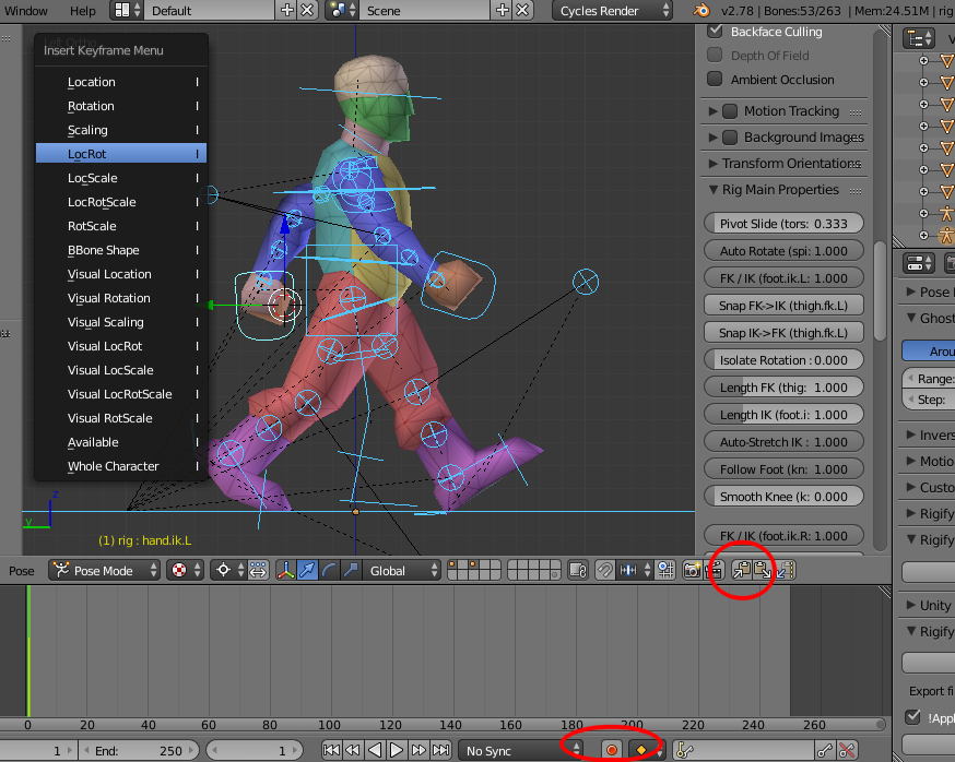
So we started off with our "extreme" pose. With auto-keying set, each time a bone or IK controller is moved, Blender automatically creates a key frame for you.
We used the IK controllers on the hands and feet to create a classic walking pose. For good measure, in pose mode, we selected all the bones in the rig and - via the Space popup menu - hit "insert keyframe". Then, with all the bones still selected, hit the copy pose button.
Then, forty frames on, we hit the "paste reversed" button. It's the second of the two paste buttons. A perfect mirror image of the pose appears.
Then, forty frames further on again, we paste the original pose (not mirrored). In the section at the bottom, we set the animation to run from frames 1-80 and hit play. Already we have a simple (albeit rather clumsy) walk animation.
Now, that's ok. But it's not brilliant. It's a bit "lifeless".
So we now need to create the "crossover pose". This is the pose, exactly half-way along the animation, where one leg crosses over the other. While we're about it, we made a few tweaks to the crossover pose.
It's at this point in a walk action, where the "front" leg is taking the entire weight of the body. It's also where the character is getting ready to "spring" into the next pose. As such, the body needs to be compressed slightly - the front leg bent slightly, ready to push off with the next step. So we grab the hips and pull them down slightly.
Because our hands are still set to IK (inverse kinematics) they remain exactly in place, even though the entire body has shifted down a little (almost as if they were holding onto some invisible bars, keeping them at their current level). So we grab each hand and pull them down, towards the floor, a little bit.
Then, forty frames further on, we paste a mirrored copy of this cross-over pose. Already our walk cycle animation looks much better.
Now that's a bit more like it. It's not perfect, but with just two major poses (mirrored at the appropriate points in the animation) our walk cycle has a lot more life in it!
If you watch the animation back, the character appears to "ride on his heels" for a long part of the walk. We would prefer his foot to be flat to the floor for a longer time during the animation.
So between the extreme and the crossover poses, we created another keyframe, this time placing the foot flat on the floor (and turning the toes a little to flatten the foot out completely).
After watching the animation through a few times more, we found a slight - ever so slight (in fact, probably not even noticeable once the character is in a game world, animated, and viewed at a distance from a slightly overhead view-point) problem. As the foot slides back, from the crossover to the extreme pose, it can dip below the floor line.
Another key frame and a quick tweak, and the animation is pretty much done. For now, anyway. There's no real character to the walk - no gait, or anything to indicate whether this is a light or heavy person. But it's a start!
In hindsight, we'd probably make this animation run over 60 frames, not eighty. As it is, the character appears to be walking quite slowly. So we should either speed it up a little, or play about with the key-frames, making the rise take longer, and the "fall" into the crossover position quicker, to indicate a slow, heavy, lumbering character.
There are probably plenty of ways we can add a little more character to the animations. But for now, we're just getting used to mixing IK and FK controllers to create simple animations for our Unity game. Next up.... getting the animations to play in Unity!
So we started off with our "extreme" pose. With auto-keying set, each time a bone or IK controller is moved, Blender automatically creates a key frame for you.
We used the IK controllers on the hands and feet to create a classic walking pose. For good measure, in pose mode, we selected all the bones in the rig and - via the Space popup menu - hit "insert keyframe". Then, with all the bones still selected, hit the copy pose button.
Then, forty frames on, we hit the "paste reversed" button. It's the second of the two paste buttons. A perfect mirror image of the pose appears.
Then, forty frames further on again, we paste the original pose (not mirrored). In the section at the bottom, we set the animation to run from frames 1-80 and hit play. Already we have a simple (albeit rather clumsy) walk animation.
So we now need to create the "crossover pose". This is the pose, exactly half-way along the animation, where one leg crosses over the other. While we're about it, we made a few tweaks to the crossover pose.
It's at this point in a walk action, where the "front" leg is taking the entire weight of the body. It's also where the character is getting ready to "spring" into the next pose. As such, the body needs to be compressed slightly - the front leg bent slightly, ready to push off with the next step. So we grab the hips and pull them down slightly.
Because our hands are still set to IK (inverse kinematics) they remain exactly in place, even though the entire body has shifted down a little (almost as if they were holding onto some invisible bars, keeping them at their current level). So we grab each hand and pull them down, towards the floor, a little bit.
Then, forty frames further on, we paste a mirrored copy of this cross-over pose. Already our walk cycle animation looks much better.
Now that's a bit more like it. It's not perfect, but with just two major poses (mirrored at the appropriate points in the animation) our walk cycle has a lot more life in it!
If you watch the animation back, the character appears to "ride on his heels" for a long part of the walk. We would prefer his foot to be flat to the floor for a longer time during the animation.
So between the extreme and the crossover poses, we created another keyframe, this time placing the foot flat on the floor (and turning the toes a little to flatten the foot out completely).
After watching the animation through a few times more, we found a slight - ever so slight (in fact, probably not even noticeable once the character is in a game world, animated, and viewed at a distance from a slightly overhead view-point) problem. As the foot slides back, from the crossover to the extreme pose, it can dip below the floor line.
Another key frame and a quick tweak, and the animation is pretty much done. For now, anyway. There's no real character to the walk - no gait, or anything to indicate whether this is a light or heavy person. But it's a start!
In hindsight, we'd probably make this animation run over 60 frames, not eighty. As it is, the character appears to be walking quite slowly. So we should either speed it up a little, or play about with the key-frames, making the rise take longer, and the "fall" into the crossover position quicker, to indicate a slow, heavy, lumbering character.
There are probably plenty of ways we can add a little more character to the animations. But for now, we're just getting used to mixing IK and FK controllers to create simple animations for our Unity game. Next up.... getting the animations to play in Unity!
Rigify for Blender with Unity
Recently we had a play about with rigging custom characters in Blender. We made some simple rigs and correctly mapped the bones to Unity's Mecanim system. This is great for rigging characters to enable them to pick up and use existing animations within Unity.
But what about animations that don't yet exist?
Blender itself can be used to create custom animations. But animating with such a simple rig can be a bit of a headache. Make a slight adjustment to just one bone and your entire character can be thrown out of whack.
To create realistic animations, we really need to be using IK (inverse kinematics) - not just FK (forward kinematics) as our simple rig provides. This is where the Blender plugin Rigify comes in really, really useful!
Starting with a blank (no bones) mesh, and with our editor in object mode, we use menu Add - Armature - Human Rig
There's a chance that the rig appears at the cursor position, ,rather than centred nicely, so set the rig (in object mode) to 0,0,0. At this stage, it doesn't matter if the rig isn't the same size as our mesh - we'll deal with that in a second.
It's debatable whether you should scale the rig, or scale the mesh to fit. We decided to leave the rig and scale the mesh to match it. It's almost there - just needs a little tweak.
We select the mesh and enter edit mode. Then select all the faces and scale the mesh up, ever so slightly. Doing things this way should make it easier for us to create similarly sized characters in future.
To save on work, we click the "x-axis mirror" option and now start to fit our rig to the mesh. While it's tempting to just grab bone nodes and move them around, we've found that rotating limbs into the arms and legs gives a nicer deform when animating the character in later stages.
So, in edit mode, we select the entire leg chain in the rig, click to place the 3d cursor at the hip joint of the leg, then use the rotate handle to position the leg bones as closely as possible to the leg mesh.
Then - just as we did with our simple rig - we move the bones "into" the mesh, grabbing and moving the ends of the bones so that the shoulder, elbow and knee joints are in the best places within the mesh. Don't forget you can rotate the view around and make sure the bones fit into the rig from the top, side and front!
With all the bones positioned, it's time to create our Rigify Rig. With the armature selected in the main window, and the armature tab selected in the treeview panel, scroll down to the Rigify Buttons entry and click the "generate" button.
After a few seconds, the Rigify Rig appears.
We're done with the "metarig" so you can hide it now...
The Rigify Rig contains loads of bones and controllers, spread across a number of different layers. While we've generated a skeleton, we haven't yet rigged it to the mesh. So we need to show the deformation bones in the Rigify Rig. Shift-Click the layer indicated, and the deformation bones should appear. If you can't see them, try turning on the x-ray option also.
Now in object mode select the mesh first, then shift-click the underlying bones/rig, then ctrl+P to parent the mesh to the rig.
We're almost done.
If everything has gone well, you should now have a controllable rig, mapped to the mesh. Select the rig and enter pose mode.
Grab one of the IK indicators around the feet or hands, and set the IK value from zero to fully one. Move the IK object around and watch your character's legs/arms move around in response to your positioning the hand/foot.
Using IK makes positioning your characters much, much easier than an entirely FK bone-chain. We're now off to have a play with the FK/IK settings in Blender and see what's involved with creating a simple walk cycle.....
But what about animations that don't yet exist?
Blender itself can be used to create custom animations. But animating with such a simple rig can be a bit of a headache. Make a slight adjustment to just one bone and your entire character can be thrown out of whack.
To create realistic animations, we really need to be using IK (inverse kinematics) - not just FK (forward kinematics) as our simple rig provides. This is where the Blender plugin Rigify comes in really, really useful!
Starting with a blank (no bones) mesh, and with our editor in object mode, we use menu Add - Armature - Human Rig
There's a chance that the rig appears at the cursor position, ,rather than centred nicely, so set the rig (in object mode) to 0,0,0. At this stage, it doesn't matter if the rig isn't the same size as our mesh - we'll deal with that in a second.
It's debatable whether you should scale the rig, or scale the mesh to fit. We decided to leave the rig and scale the mesh to match it. It's almost there - just needs a little tweak.
We select the mesh and enter edit mode. Then select all the faces and scale the mesh up, ever so slightly. Doing things this way should make it easier for us to create similarly sized characters in future.
To save on work, we click the "x-axis mirror" option and now start to fit our rig to the mesh. While it's tempting to just grab bone nodes and move them around, we've found that rotating limbs into the arms and legs gives a nicer deform when animating the character in later stages.
So, in edit mode, we select the entire leg chain in the rig, click to place the 3d cursor at the hip joint of the leg, then use the rotate handle to position the leg bones as closely as possible to the leg mesh.
Then - just as we did with our simple rig - we move the bones "into" the mesh, grabbing and moving the ends of the bones so that the shoulder, elbow and knee joints are in the best places within the mesh. Don't forget you can rotate the view around and make sure the bones fit into the rig from the top, side and front!
With all the bones positioned, it's time to create our Rigify Rig. With the armature selected in the main window, and the armature tab selected in the treeview panel, scroll down to the Rigify Buttons entry and click the "generate" button.
After a few seconds, the Rigify Rig appears.
We're done with the "metarig" so you can hide it now...
The Rigify Rig contains loads of bones and controllers, spread across a number of different layers. While we've generated a skeleton, we haven't yet rigged it to the mesh. So we need to show the deformation bones in the Rigify Rig. Shift-Click the layer indicated, and the deformation bones should appear. If you can't see them, try turning on the x-ray option also.
Now in object mode select the mesh first, then shift-click the underlying bones/rig, then ctrl+P to parent the mesh to the rig.
We're almost done.
If everything has gone well, you should now have a controllable rig, mapped to the mesh. Select the rig and enter pose mode.
Grab one of the IK indicators around the feet or hands, and set the IK value from zero to fully one. Move the IK object around and watch your character's legs/arms move around in response to your positioning the hand/foot.
Using IK makes positioning your characters much, much easier than an entirely FK bone-chain. We're now off to have a play with the FK/IK settings in Blender and see what's involved with creating a simple walk cycle.....
Monday, 14 November 2016
Creating a simple mecanim-ready rig for Unity with Blender
Since getting our two-screen PC setup working, we've been doing quite a bit of messing about with Blender. As well as modelling some cool armour add-ons for an existing Asset Store character, we've been playing about with rigs and bones and creating animations (spoiler alert - animating is hard).
There are plenty of tutorials and rigs for Blender all over the intertubes - many of them make rigging look like hard work. Some of them even tell you it is. But actually rigging a character for use with (pre-existing) mecanim animations isn't that onerous at all.
The trick is to make sure you're in the correct mode in Blender when creating and editing the bones and meshes. We threw together a quick rig in Blender, exported the model into Unity and had it picking up the mecanim animations in next to no time!
I guess we all have to start somewhere, so this is how I did it. It might not be "right". It might differet to others do it. It might even be the same. But this is how I got it to work.
First things first, we need a mesh. This is a character I nicked from an existing Asset store (though modified and with some UVs mapped to it). With the mesh in position (at 0,0,0 and rotated to zero) we need to add some bones. Let's start with the first one.
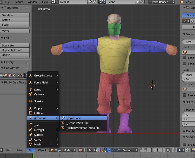
In object mode, menu Add - Amature - Single Bone
And, like magic, a bone appears.
If the bone appears hidden, or inside the mesh, we need to make it visible from all angles, by ticking the "x-ray" box in the object tree. With the bone selected, go to the tree panel and select the object tab, Scroll down the list and tick the x-ray box. The bone should now be visible, no matter which angle you view your model from.
With the single bone selected, change from Object mode to Edit mode using the little menu at the bottom. Select the head of the bone and place it roughly where the neck will start. Place the tail of the bone below where the hips will end.
Now here's where one of the really nice things about Blender comes in. Instead of trying to learn and remember a million and one keyboard shortcuts (some of those online tutorials just give a stream of Ctrl+ this and Alt+Shift+that) you can simply hit the space bar.
A pop up menu lets you type in what you want. The search results are (usually) context sensitive. So with just a few keystrokes, you can usually find what you're looking for.
With the entire bone selected (but still in edit mode) hit space and type "sub"
We're going to split the back bone into three pieces. Mecanim likes bodies split into three. So we choose armature - subdivide (notice how the search results change if you have a different object selected, or are in a different mode)
And change the number of cuts to two (we want the backbone to be in three pieces, so need to cut it twice)
Now we need to create some legs. Before going any further, let's turn on "x-axis mirroring" so that as we build the armature on one side of the character, Blender does the same amount of work for us, on the other side.
In edit mode, with any bone selected, go to the "options" tab in the tools panel and select X-axis mirror. Now, any operations we perform on our rig will be repeated on the opposite side of the character.
Let's start with a leg. Select just the node between the hips (lowest bone) and the abdomen (middle bone). If either of the entire bones light up, you need to select just the connection point, not the entire bone. Hit the space bar and type "extrude". Select Armature - Extrude. You can see that there's also a keyboard shortcut to achieve the same - just press E to start an extrusion.
Move the mouse around and when the new bone is in the right place, simply left-click to create the new (extruded) bone. Now select the new bone entirely, and from the tree panel, select the "bone" tab. Scroll down and untick the "connected" tickbox.
Now we can move the new leg bone around without affecting the rest of the bones. A dotted line shows us where the bone originated (and its parent) but by disconnecting the bone, it doesn't have to start/end connected to a previous bone.
Now- what about that x-axis mirror? Where's that gone?
Well, for that to work, it requires our bones to be named using a specific convention. Basically if you move a bone that ends in .L or _L, then any bone with the same name but a .R or _R suffix are moved/scaled/rotated at the same time. So you can name the first bone, with the suffix _L then create a second bone (extruding from the abdomen as before) and rename it with the suffix _R.
Then, as you move/rotate one bone, you should see the other bone reacting. An alternative approach would be to use Shift+E to extrude the bone in the first place. Doing this actually creates two bones - one with a _L suffix and one with a _R suffix; so as you move/scale one, the other updates in realtime.
With two leg bones - each with the suffix _L or _R - we need to subdivide these, just as we did with the backbone. This time, we split each leg into just two parts, with a single cut.
Then with the root of the leg selected, Shift+E to extrude a new bone towards the toe (or use the space menu and type Extrude on each leg, renaming each new bone with the appropriate _L and _R suffixes). It may be easier to switch to ortho-left view (numberpad 3). Select the new bone and subdivide into two.
Next, with the tip of the top backbone selected, Shift+Extrude the arm bone(s).
And subdivide into four parts (three cuts). The first part of the bone-chain is the collarbone. The second is the top of the arm or bicep. The third bone is the lower arm or forearm. The fourth bone is the hand controller.
Our character has fists, not fully articulated hands. So we're not going to bother with hands, fingers and thumb bones - a single bone to rotate the entire fist will suffice for our animations. Move the connection points between the bones to the correct places for the shoulder, elbow and wrist joints.
Don't forget to rotate the charcter and make sure that the bones are fully inside the mesh - not just from the front view, but from the side and top views as well. Depending on the mesh, you might benefit from disconnecting the shoulder joint/upper arm bone from the collarbone(s).
Lastly, turn off x-axis mirror and extrude the top of the backbone into the head. Sub-divide to create two parts. Move the connection between the two new bones to create a neck bone and a larger head bone.
Don't forget to shift into side-view to move the bone end-points forwards and backwards, especially when positioning the neck and head bones.
While it may be prudent to re-name bones as we go, we tend to do all the bone renaming at the end, working systematically through the entire skeleton, renaming each bone in turn.
Our bone names are:
Mirrored bones are renamed, but using the .R suffix.
At this point, you can go into Pose mode and move the skeleton around.
But the mesh isn't rigged to the skeleton. To do this, we go into object mode and select our mesh first. Then shift-click to select the bones (the entire skeleton should highlight, indicating you're in object mode - if just a single bone lights up, you're probably still in edit or pose mode!)
On the keyboard, hit Ctrl+P and select Set Parent To - Armature Deform - With automatic weights. Now, as you move the bones around, the mesh should follow.
Save the file.
Copy it to your Unity project Assets folder.
Open Unity.
After starting up, Unity will automagically import your new Blender character. Select your Blender character from the project panel and in the Inspector window, click the "Rig" button. Set the type to humanoid and hit "configure".
After a few prompts to save and apply changes, you should see how well Unity has imported the new model. If all has gone well, the entire character should be green.
Hit the Muscles & Settings button to check that the character deformations are correctly applied when the bones are moved around.
If your character is correctly rigged (and it should be if you've followed the steps carefully) moving the sliders should animate the floating character properly. When done, scroll down the inspector panel and click the "done" button.
Now, drag an instance of your new character into the Unity world stage. Assign a mecanim controller and apply any mecanim-compatible animation. Hit play and watch your new character come to life!
Here's our character playing a full cycle of fighting animations, created by a third-party.
Ta-da!
There are plenty of tutorials and rigs for Blender all over the intertubes - many of them make rigging look like hard work. Some of them even tell you it is. But actually rigging a character for use with (pre-existing) mecanim animations isn't that onerous at all.
The trick is to make sure you're in the correct mode in Blender when creating and editing the bones and meshes. We threw together a quick rig in Blender, exported the model into Unity and had it picking up the mecanim animations in next to no time!
I guess we all have to start somewhere, so this is how I did it. It might not be "right". It might differet to others do it. It might even be the same. But this is how I got it to work.
First things first, we need a mesh. This is a character I nicked from an existing Asset store (though modified and with some UVs mapped to it). With the mesh in position (at 0,0,0 and rotated to zero) we need to add some bones. Let's start with the first one.
In object mode, menu Add - Amature - Single Bone
And, like magic, a bone appears.
If the bone appears hidden, or inside the mesh, we need to make it visible from all angles, by ticking the "x-ray" box in the object tree. With the bone selected, go to the tree panel and select the object tab, Scroll down the list and tick the x-ray box. The bone should now be visible, no matter which angle you view your model from.
With the single bone selected, change from Object mode to Edit mode using the little menu at the bottom. Select the head of the bone and place it roughly where the neck will start. Place the tail of the bone below where the hips will end.
Now here's where one of the really nice things about Blender comes in. Instead of trying to learn and remember a million and one keyboard shortcuts (some of those online tutorials just give a stream of Ctrl+ this and Alt+Shift+that) you can simply hit the space bar.
A pop up menu lets you type in what you want. The search results are (usually) context sensitive. So with just a few keystrokes, you can usually find what you're looking for.
With the entire bone selected (but still in edit mode) hit space and type "sub"
We're going to split the back bone into three pieces. Mecanim likes bodies split into three. So we choose armature - subdivide (notice how the search results change if you have a different object selected, or are in a different mode)
And change the number of cuts to two (we want the backbone to be in three pieces, so need to cut it twice)
Now we need to create some legs. Before going any further, let's turn on "x-axis mirroring" so that as we build the armature on one side of the character, Blender does the same amount of work for us, on the other side.
In edit mode, with any bone selected, go to the "options" tab in the tools panel and select X-axis mirror. Now, any operations we perform on our rig will be repeated on the opposite side of the character.
Let's start with a leg. Select just the node between the hips (lowest bone) and the abdomen (middle bone). If either of the entire bones light up, you need to select just the connection point, not the entire bone. Hit the space bar and type "extrude". Select Armature - Extrude. You can see that there's also a keyboard shortcut to achieve the same - just press E to start an extrusion.
Move the mouse around and when the new bone is in the right place, simply left-click to create the new (extruded) bone. Now select the new bone entirely, and from the tree panel, select the "bone" tab. Scroll down and untick the "connected" tickbox.
Now we can move the new leg bone around without affecting the rest of the bones. A dotted line shows us where the bone originated (and its parent) but by disconnecting the bone, it doesn't have to start/end connected to a previous bone.
Now- what about that x-axis mirror? Where's that gone?
Well, for that to work, it requires our bones to be named using a specific convention. Basically if you move a bone that ends in .L or _L, then any bone with the same name but a .R or _R suffix are moved/scaled/rotated at the same time. So you can name the first bone, with the suffix _L then create a second bone (extruding from the abdomen as before) and rename it with the suffix _R.
Then, as you move/rotate one bone, you should see the other bone reacting. An alternative approach would be to use Shift+E to extrude the bone in the first place. Doing this actually creates two bones - one with a _L suffix and one with a _R suffix; so as you move/scale one, the other updates in realtime.
With two leg bones - each with the suffix _L or _R - we need to subdivide these, just as we did with the backbone. This time, we split each leg into just two parts, with a single cut.
Then with the root of the leg selected, Shift+E to extrude a new bone towards the toe (or use the space menu and type Extrude on each leg, renaming each new bone with the appropriate _L and _R suffixes). It may be easier to switch to ortho-left view (numberpad 3). Select the new bone and subdivide into two.
Next, with the tip of the top backbone selected, Shift+Extrude the arm bone(s).
And subdivide into four parts (three cuts). The first part of the bone-chain is the collarbone. The second is the top of the arm or bicep. The third bone is the lower arm or forearm. The fourth bone is the hand controller.
Our character has fists, not fully articulated hands. So we're not going to bother with hands, fingers and thumb bones - a single bone to rotate the entire fist will suffice for our animations. Move the connection points between the bones to the correct places for the shoulder, elbow and wrist joints.
Don't forget to rotate the charcter and make sure that the bones are fully inside the mesh - not just from the front view, but from the side and top views as well. Depending on the mesh, you might benefit from disconnecting the shoulder joint/upper arm bone from the collarbone(s).
Lastly, turn off x-axis mirror and extrude the top of the backbone into the head. Sub-divide to create two parts. Move the connection between the two new bones to create a neck bone and a larger head bone.
Don't forget to shift into side-view to move the bone end-points forwards and backwards, especially when positioning the neck and head bones.
While it may be prudent to re-name bones as we go, we tend to do all the bone renaming at the end, working systematically through the entire skeleton, renaming each bone in turn.
Our bone names are:
- head, neck
- collarbone.L
- upperArm.L
- lowerArm.L
- hand.L
- chest
- abdomen
- hips
- upperLeg.L
- lowerLeg.L
- foot.L
- toes.L
Mirrored bones are renamed, but using the .R suffix.
At this point, you can go into Pose mode and move the skeleton around.
But the mesh isn't rigged to the skeleton. To do this, we go into object mode and select our mesh first. Then shift-click to select the bones (the entire skeleton should highlight, indicating you're in object mode - if just a single bone lights up, you're probably still in edit or pose mode!)
On the keyboard, hit Ctrl+P and select Set Parent To - Armature Deform - With automatic weights. Now, as you move the bones around, the mesh should follow.
Save the file.
Copy it to your Unity project Assets folder.
Open Unity.
After starting up, Unity will automagically import your new Blender character. Select your Blender character from the project panel and in the Inspector window, click the "Rig" button. Set the type to humanoid and hit "configure".
After a few prompts to save and apply changes, you should see how well Unity has imported the new model. If all has gone well, the entire character should be green.
Hit the Muscles & Settings button to check that the character deformations are correctly applied when the bones are moved around.
If your character is correctly rigged (and it should be if you've followed the steps carefully) moving the sliders should animate the floating character properly. When done, scroll down the inspector panel and click the "done" button.
Now, drag an instance of your new character into the Unity world stage. Assign a mecanim controller and apply any mecanim-compatible animation. Hit play and watch your new character come to life!
Here's our character playing a full cycle of fighting animations, created by a third-party.
Ta-da!
Sunday, 13 November 2016
3D modelling PC from salvaged parts
A little while back, 3D Dave was having a bit of a clearout. He gave us a P8Z77-LX motherboard, CPU and Zotac GeoForce GTX graphics card.
A quick hit on eBay and for about fifty quid we had some memory (8Gb) and a (400Gb) hard-drive ordered. An old modular power supply completed the rig and a copy of Windows 10 for just twenty quid at computerbuilders.co.uk meant we were ready to go, and fully legit (really, at these kind of prices, does anyone still mess about with torrents for software any more?)
Windows 10 installs much more quickly (from a usb key) than previous versions ever did; less than an hour later and we had a spanky brand new PC running both Unity and Blender, complete with a twin-screen setup, ready for some serious modelling/rigging/animation.
I've never really understood why Steve raves so much about his multi-screen set-up (three large monitors and a smaller one for emails). But after playing about with two monitors (and a half-decent PC) I can see exactly what he was talking about.
In fact, the only question I have left is - if my graphics cards has twin DIV outputs (currently driving the twin monitor set-up) can I shove a third into the HDMI slot?
Multi-screen computer FTW!
A quick hit on eBay and for about fifty quid we had some memory (8Gb) and a (400Gb) hard-drive ordered. An old modular power supply completed the rig and a copy of Windows 10 for just twenty quid at computerbuilders.co.uk meant we were ready to go, and fully legit (really, at these kind of prices, does anyone still mess about with torrents for software any more?)
Windows 10 installs much more quickly (from a usb key) than previous versions ever did; less than an hour later and we had a spanky brand new PC running both Unity and Blender, complete with a twin-screen setup, ready for some serious modelling/rigging/animation.
I've never really understood why Steve raves so much about his multi-screen set-up (three large monitors and a smaller one for emails). But after playing about with two monitors (and a half-decent PC) I can see exactly what he was talking about.
In fact, the only question I have left is - if my graphics cards has twin DIV outputs (currently driving the twin monitor set-up) can I shove a third into the HDMI slot?
Multi-screen computer FTW!
Wednesday, 9 November 2016
Blood Bowl is back - and maybe, so too, might our electronic board game?
About a million years ago, we made a simple electronic device to keep track of plays and character stats for the tabletop fantasy football game Blood Bowl. At the time, the game was pretty much out of favour, but has since seen not just one, but two digital versions of the game.
Our version wasn't much to write home about, but did start a many-years-long search for a still-as-yet-elusive tabletop/computer cross-over.
We came close. We even made a working prototype and got a massive 48 x 64 square playing surface working. But then creating games for heavily-copyright-protected content was always a bit of an obstacle.
So while we're trying to find a way of releasing the hardware designs under an open source licence, we've been distracting ourselves with creating assets for a potential Unity game. Even if it comes to nothing, 3d modelling is something that we really should have looked at a long time ago but just never go around to it.
With the number of 3d printers and potential for all kinds of awesome tabletop terrain having exploded in recent years, it was really only a matter of time before one of us succumbed and had a go at modelling some game assets. Steve, of course, has been an avid 3DS Max user for a long time - creating all kinds of awesome structures and models for his 3D printer. I decided to go the other route and try to tackle Blender....
Using a number of online sources to get started, I managed to import a couple of pre-bought Unity assets (via the .fbx importer). But what to model....?
Which brings us back to Blood Bowl.
Games Workshop are releasing a new version late in 2016 (there's talk that it might be as early as 19th Nov). It's the original game, repackaged, but with some really nice looking miniatures. Which means it's probably going to get a bit boring after a couple of plays. But it also means that there's a massive amount of interest around it already.
So - if we're going to produce a relatively simple, over-in-an-hour kind of game to put to use with our electronic hardware - why not some Blood Bowl characters? We've already bought some low-poly cartoon Orcs that will look great as fantasy football players.
Unfortunately, fantasy-style humans, in armour, with spikes and sporting American Football helmets are not so easy to come by. So that's where we started.
With a basic human character, I then added some shoulder pads, a helmet, and plenty of spikes. Now Blender is a massive topic and there are no end of online tutorials (plus, I'm still not entirely sure about what I'm doing, so wouldn't like to put together a how-to just yet). But here's a preview of my first low-poly Blood Bowl human, complete with basic UVs applied.
It's a total of 1500 polys, including the optional helmet, shoulder pads, armour and spikes. The idea is that, in game, (if it ever gets made) the player can add or remove armour to reflect the character's playing position. A thrower or a catcher might have little or no armour, whereas a blitzer or a blocker would have plenty of armour (and lots of spikes too!)
In a first attempt at UV unwrapping, we came up with this monstrosity:
But it applied nicely to the 3d model (as shown in the image higher up). What worked really well was simply taking a Google photo and dropping it onto the UV image. In this case, I simply Googled "boot treads" in images, found a photo of the sole of a boot and dropped it onto the UV image.
It's a long way to go before we're producing models up to the standard of those in the Asset store. But for now, we're going to say that the modelling is done, and have a look at rigging and animating our little character in Blender, before exporting it for use in Unity.
Our version wasn't much to write home about, but did start a many-years-long search for a still-as-yet-elusive tabletop/computer cross-over.
We came close. We even made a working prototype and got a massive 48 x 64 square playing surface working. But then creating games for heavily-copyright-protected content was always a bit of an obstacle.
So while we're trying to find a way of releasing the hardware designs under an open source licence, we've been distracting ourselves with creating assets for a potential Unity game. Even if it comes to nothing, 3d modelling is something that we really should have looked at a long time ago but just never go around to it.
With the number of 3d printers and potential for all kinds of awesome tabletop terrain having exploded in recent years, it was really only a matter of time before one of us succumbed and had a go at modelling some game assets. Steve, of course, has been an avid 3DS Max user for a long time - creating all kinds of awesome structures and models for his 3D printer. I decided to go the other route and try to tackle Blender....
Using a number of online sources to get started, I managed to import a couple of pre-bought Unity assets (via the .fbx importer). But what to model....?
Which brings us back to Blood Bowl.
Games Workshop are releasing a new version late in 2016 (there's talk that it might be as early as 19th Nov). It's the original game, repackaged, but with some really nice looking miniatures. Which means it's probably going to get a bit boring after a couple of plays. But it also means that there's a massive amount of interest around it already.
So - if we're going to produce a relatively simple, over-in-an-hour kind of game to put to use with our electronic hardware - why not some Blood Bowl characters? We've already bought some low-poly cartoon Orcs that will look great as fantasy football players.
Although crude, these low-poly Orcs will be perfect for use in a fantasy football game where many characters can appear on screen at the same time - so they'll be pretty zoomed out
Unfortunately, fantasy-style humans, in armour, with spikes and sporting American Football helmets are not so easy to come by. So that's where we started.
With a basic human character, I then added some shoulder pads, a helmet, and plenty of spikes. Now Blender is a massive topic and there are no end of online tutorials (plus, I'm still not entirely sure about what I'm doing, so wouldn't like to put together a how-to just yet). But here's a preview of my first low-poly Blood Bowl human, complete with basic UVs applied.
It's a total of 1500 polys, including the optional helmet, shoulder pads, armour and spikes. The idea is that, in game, (if it ever gets made) the player can add or remove armour to reflect the character's playing position. A thrower or a catcher might have little or no armour, whereas a blitzer or a blocker would have plenty of armour (and lots of spikes too!)
in Blood Bowl, the catchers is much more lightly armoured than players such as Blockers and Blitzers.
In a first attempt at UV unwrapping, we came up with this monstrosity:
But it applied nicely to the 3d model (as shown in the image higher up). What worked really well was simply taking a Google photo and dropping it onto the UV image. In this case, I simply Googled "boot treads" in images, found a photo of the sole of a boot and dropped it onto the UV image.
It's a long way to go before we're producing models up to the standard of those in the Asset store. But for now, we're going to say that the modelling is done, and have a look at rigging and animating our little character in Blender, before exporting it for use in Unity.
Saturday, 5 November 2016
More messing about with IR
We've been using IR quite a bit lately, for a project that involves an object which moves, and tells a "base" object that it's resting in about it's current state. The idea is that the base object lights up to tell the user what state the first object is in.
Because the object can spin, rotate and generally move around, we had to implement a wireless method of sending information between the base and the object. Radio seemed a bit overkill (and, since the object is battery powered, we wanted to reduce the current draw as much as possible). IR seemed like the perfect solution.
In fact, we had a working solution a few weeks back, using tiny reflective sensors. But instead of sending a signal and reading the reflected response, both the object and the base had a QRE1113 sensor inside them - so the base didn't read it's own reflected signal, it received a signal sent from the object.
Everything seemed fine. Except the distance between the sensors was critical. At this distance, everything worked great.
But at this distance...
... even after ensuring that the sensors are perfectly in line, the signal often didn't make it from one to the other. After inspecting the IR LED in the sensor (using a phone camera) the amount of light emitted appears as a tiny, tiny dot. Basically, these reflective sensors are good up to about 8-10mm. Anything more than that and the signal gets lost - or occasionally corrupted.
We wanted to increase the distance between our sensors so needed something with a bit more oomph. A simple IR LED and IR phototransistor seemed like a good idea.
Except these were very sensitive to the angle of two being absolutely accurate. Even just a couple of degrees off and the phototransistor stopped responding to the IR LED.
So Steve suggested using the Vishay 38khz IR receivers, most commonly found in TV units (to decode remote control button presses). These are able to receive IR bounced around from all over the place!
Not only do they work if you point an LED directly at a sensor....
They also work at greater distances, and even at 90 degrees or more! Until we put our LED/sensor combo inside a container, they could receive IR from the LED no matter which angle they were facing. But just being able to consistently receive IR from the object was only half the problem - we also wanted to ensure that both the base and the object were in sync (something that wasn't always possible with just single-way communication)
Using a send and receive pair in both the object and the base, we modified the firmware slightly, to use a call-and-response method of keeping the two in sync.
Originally we just had the object report it's status and the base would update to indicate to the user the current state of the object. But sometimes the object would change state and the base failed to receive the updated status. The two would often go out of sync.
With this new hardware, the messaging process is going to be:
a) the object detects a change
b) the object sends a message to the base
c) the base updates its' display (LEDs)
d) the base returns the message to the object (up to three times)
e) the object updates its status when it receives any one of these messages.
This method of send and receive ensures that if the message from the object doesn't get to the base (for whatever reason) the two remain in sync. It's almost like the object is asking "can I go to state x" and the base confirms "yes, you can now move to state x". Only when the response message is received does does the object update its status. This should ensure that the display on the base matches the status of the object that initiated the change.
Of course it's not 100% foolproof - there's a chance that the message from the base to the object gets lost and they go out of sync again. But it's less likely to happen because the response message is sent almost instantly (and is repeated up to three times). So as soon as the object sends its "request" message, the base responds (within about 50ms). As long as the object hasn't moved too much within this tiny time frame, it should be able to receive at least one of the three response messages.
Here's how we set up our two Arduinos:
And the firmware (the same firmware is uploaded to both and the state of the button pin checked on boot up to decide the "role" of the device- either base or object).
#include <IRLib.h>
//Create a receiver object to listen on pin 10
IRrecv My_Receiver(10);
IRsend My_Sender;
IRdecode My_Decoder;
#define IR_RECEIVE_ALL_THE_TIME 0
#define IR_SEND_THEN_RECEIVE 1
#define IR_RECEIVE_FOR_1_SEC 2
#define IR_SEND_RELAY 3
int button_pin=12;
bool is_sender = true;
int ir_state = IR_RECEIVE_ALL_THE_TIME;
long ir_value = 0xf578;
long ir_last_value = 0x0000;
long time_start_listening;
long time_now;
long time_diff;
void sendIRValue(){
Serial.print(F("Sending: "));
Serial.println(ir_value, HEX);
My_Sender.send(RC5, ir_value, 13);
delay(10);
My_Sender.send(RC5, ir_value, 13);
}
void parseMessage(){
// now what to do with the received IR value?
Serial.print(F("Parsing: "));
Serial.println(ir_value, HEX);
// for testing the base, just send this message back out
// (for the sender, don't do anything)
if(is_sender==false){
delay(2);
ir_state = IR_SEND_RELAY;
}else{
if(ir_value == ir_last_value){
Serial.println(F("Nothing to do, repeat value received"));
}else{
Serial.println(F("Change language"));
}
}
ir_last_value = ir_value;
}
void setup() {
Serial.begin(19200);
pinMode(button_pin, INPUT_PULLUP);
My_Receiver.enableIRIn(); // Start the receiver
// this is just for testing
int b = digitalRead(button_pin);
if(b == LOW){
is_sender=false;
Serial.println(F("I am the base"));
}else{
Serial.println(F("I am the sender"));
}
}
void loop() {
int b;
time_now = millis();
// this is just for testing
b = digitalRead(button_pin);
if(b==LOW && is_sender==true){
// debounce the button press
delay(10);
b = digitalRead(button_pin);
if(b==LOW){
// wait for release
while(b==LOW){ b = digitalRead(button_pin); }
// now send a blast of IR
ir_state = IR_SEND_THEN_RECEIVE;
}
}
// deal with any incoming IR (if necessary)
switch(ir_state){
//-----------------------------
case IR_RECEIVE_ALL_THE_TIME:
//-----------------------------
if (My_Receiver.GetResults(&My_Decoder)) {
My_Decoder.decode(); //Decode the data
b = My_Decoder.value & 0x1fff; // our data is only 13 bits long
if(b > 0){
ir_value = b;
parseMessage();
}
My_Receiver.resume(); //Restart the receiver
}
break;
//-----------------------------
case IR_SEND_THEN_RECEIVE:
//-----------------------------
delay(20);
sendIRValue();
// now we listen for a response for a second or two
time_start_listening = millis();
// re-enable the receiver
My_Receiver.enableIRIn();
ir_state = IR_RECEIVE_FOR_1_SEC;
break;
//-----------------------------
case IR_SEND_RELAY:
//-----------------------------
delay(50);
sendIRValue();
// send the response message another couple of
// times in case one of them burps.
delay(50);
sendIRValue();
delay(50);
sendIRValue();
// re-enable the receiver
My_Receiver.enableIRIn();
ir_state = IR_RECEIVE_ALL_THE_TIME;
break;
//-----------------------------------
case IR_RECEIVE_FOR_1_SEC:
//-----------------------------------
if (My_Receiver.GetResults(&My_Decoder)) {
My_Decoder.decode(); //Decode the data
b = My_Decoder.value & 0x1fff; // our data is only 13 bits long
if(b > 0){
ir_value = b;
parseMessage();
// now leave this state
ir_state = 99;
}
My_Receiver.resume(); //Restart the receiver
}
time_diff = time_now - time_start_listening;
if(time_diff > 500){
// leave this state
Serial.println(F("Leaving receive state"));
ir_state = 99;
}
break;
}
}
Because the object can spin, rotate and generally move around, we had to implement a wireless method of sending information between the base and the object. Radio seemed a bit overkill (and, since the object is battery powered, we wanted to reduce the current draw as much as possible). IR seemed like the perfect solution.
In fact, we had a working solution a few weeks back, using tiny reflective sensors. But instead of sending a signal and reading the reflected response, both the object and the base had a QRE1113 sensor inside them - so the base didn't read it's own reflected signal, it received a signal sent from the object.
Everything seemed fine. Except the distance between the sensors was critical. At this distance, everything worked great.
But at this distance...
... even after ensuring that the sensors are perfectly in line, the signal often didn't make it from one to the other. After inspecting the IR LED in the sensor (using a phone camera) the amount of light emitted appears as a tiny, tiny dot. Basically, these reflective sensors are good up to about 8-10mm. Anything more than that and the signal gets lost - or occasionally corrupted.
We wanted to increase the distance between our sensors so needed something with a bit more oomph. A simple IR LED and IR phototransistor seemed like a good idea.
Except these were very sensitive to the angle of two being absolutely accurate. Even just a couple of degrees off and the phototransistor stopped responding to the IR LED.
So Steve suggested using the Vishay 38khz IR receivers, most commonly found in TV units (to decode remote control button presses). These are able to receive IR bounced around from all over the place!
Not only do they work if you point an LED directly at a sensor....
They also work at greater distances, and even at 90 degrees or more! Until we put our LED/sensor combo inside a container, they could receive IR from the LED no matter which angle they were facing. But just being able to consistently receive IR from the object was only half the problem - we also wanted to ensure that both the base and the object were in sync (something that wasn't always possible with just single-way communication)
Using a send and receive pair in both the object and the base, we modified the firmware slightly, to use a call-and-response method of keeping the two in sync.
Originally we just had the object report it's status and the base would update to indicate to the user the current state of the object. But sometimes the object would change state and the base failed to receive the updated status. The two would often go out of sync.
With this new hardware, the messaging process is going to be:
a) the object detects a change
b) the object sends a message to the base
c) the base updates its' display (LEDs)
d) the base returns the message to the object (up to three times)
e) the object updates its status when it receives any one of these messages.
This method of send and receive ensures that if the message from the object doesn't get to the base (for whatever reason) the two remain in sync. It's almost like the object is asking "can I go to state x" and the base confirms "yes, you can now move to state x". Only when the response message is received does does the object update its status. This should ensure that the display on the base matches the status of the object that initiated the change.
Of course it's not 100% foolproof - there's a chance that the message from the base to the object gets lost and they go out of sync again. But it's less likely to happen because the response message is sent almost instantly (and is repeated up to three times). So as soon as the object sends its "request" message, the base responds (within about 50ms). As long as the object hasn't moved too much within this tiny time frame, it should be able to receive at least one of the three response messages.
Here's how we set up our two Arduinos:
Send Receive 38khz by chris_holden2495 on Scribd
And the firmware (the same firmware is uploaded to both and the state of the button pin checked on boot up to decide the "role" of the device- either base or object).
#include <IRLib.h>
//Create a receiver object to listen on pin 10
IRrecv My_Receiver(10);
IRsend My_Sender;
IRdecode My_Decoder;
#define IR_RECEIVE_ALL_THE_TIME 0
#define IR_SEND_THEN_RECEIVE 1
#define IR_RECEIVE_FOR_1_SEC 2
#define IR_SEND_RELAY 3
int button_pin=12;
bool is_sender = true;
int ir_state = IR_RECEIVE_ALL_THE_TIME;
long ir_value = 0xf578;
long ir_last_value = 0x0000;
long time_start_listening;
long time_now;
long time_diff;
void sendIRValue(){
Serial.print(F("Sending: "));
Serial.println(ir_value, HEX);
My_Sender.send(RC5, ir_value, 13);
delay(10);
My_Sender.send(RC5, ir_value, 13);
}
void parseMessage(){
// now what to do with the received IR value?
Serial.print(F("Parsing: "));
Serial.println(ir_value, HEX);
// for testing the base, just send this message back out
// (for the sender, don't do anything)
if(is_sender==false){
delay(2);
ir_state = IR_SEND_RELAY;
}else{
if(ir_value == ir_last_value){
Serial.println(F("Nothing to do, repeat value received"));
}else{
Serial.println(F("Change language"));
}
}
ir_last_value = ir_value;
}
void setup() {
Serial.begin(19200);
pinMode(button_pin, INPUT_PULLUP);
My_Receiver.enableIRIn(); // Start the receiver
// this is just for testing
int b = digitalRead(button_pin);
if(b == LOW){
is_sender=false;
Serial.println(F("I am the base"));
}else{
Serial.println(F("I am the sender"));
}
}
void loop() {
int b;
time_now = millis();
// this is just for testing
b = digitalRead(button_pin);
if(b==LOW && is_sender==true){
// debounce the button press
delay(10);
b = digitalRead(button_pin);
if(b==LOW){
// wait for release
while(b==LOW){ b = digitalRead(button_pin); }
// now send a blast of IR
ir_state = IR_SEND_THEN_RECEIVE;
}
}
// deal with any incoming IR (if necessary)
switch(ir_state){
//-----------------------------
case IR_RECEIVE_ALL_THE_TIME:
//-----------------------------
if (My_Receiver.GetResults(&My_Decoder)) {
My_Decoder.decode(); //Decode the data
b = My_Decoder.value & 0x1fff; // our data is only 13 bits long
if(b > 0){
ir_value = b;
parseMessage();
}
My_Receiver.resume(); //Restart the receiver
}
break;
//-----------------------------
case IR_SEND_THEN_RECEIVE:
//-----------------------------
delay(20);
sendIRValue();
// now we listen for a response for a second or two
time_start_listening = millis();
// re-enable the receiver
My_Receiver.enableIRIn();
ir_state = IR_RECEIVE_FOR_1_SEC;
break;
//-----------------------------
case IR_SEND_RELAY:
//-----------------------------
delay(50);
sendIRValue();
// send the response message another couple of
// times in case one of them burps.
delay(50);
sendIRValue();
delay(50);
sendIRValue();
// re-enable the receiver
My_Receiver.enableIRIn();
ir_state = IR_RECEIVE_ALL_THE_TIME;
break;
//-----------------------------------
case IR_RECEIVE_FOR_1_SEC:
//-----------------------------------
if (My_Receiver.GetResults(&My_Decoder)) {
My_Decoder.decode(); //Decode the data
b = My_Decoder.value & 0x1fff; // our data is only 13 bits long
if(b > 0){
ir_value = b;
parseMessage();
// now leave this state
ir_state = 99;
}
My_Receiver.resume(); //Restart the receiver
}
time_diff = time_now - time_start_listening;
if(time_diff > 500){
// leave this state
Serial.println(F("Leaving receive state"));
ir_state = 99;
}
break;
}
}
Subscribe to:
Posts (Atom)