Wednesday, 29 June 2011

Multiple touch sensitive inputs

In a previous post we talked about how to use a darlington transistor to create a touch sensitive switch.

For a device with multiple touch-sensitive inputs, it seems obvious that we repeat the single input for each pin we want to use as a touch sensor:


However, for each input our component count increases.
In the example above, we're using PORTB on the microcontroller, which has a built-in pull-up resistor on each input pin. If we need to use a different port, or want to use more than 8 inputs, we're going to have to add a pull-up resistor on each input pin. Also required - though not shown on the diagram above for the sake of simplicity - is a 1M pull-down resistor on the base pin of each darlington transistor.
So for each additional input, we're introducing three extra components.

It's worth noting, at this point, that for each touch sensitive input, we need two pads per input: one pad connected to the base pin on a transistor, and one pad connected to the 5V supply (the user touches and effectively creates a bridge between the 5V supply and the base input pin).

However, we can simplify our design massively by swapping the pads around:
instead of a fixed 5V supply and multiple darlington transistors, we can use a single transistor and multiple, variable 5V supplies. How to do this?
We turn each potential input pin to an OUTPUT and use this output to drive what would otherwise be a fixed 5V supply on the first pad. So each pair of pads that make up a touch-sensitive switch consist of an output pin (from the microcontroller) and a pin connected to the base of the darlington transistor.

a simple PIC/usb device with 16 touch sensitive inputs

Every touch contact would consist of a pair of pins/pads - one going to each of the numbered pads (PAD1, PAD2 etc) and the other a common input (COM_INPUT) so there would be a total of 16 COM_INPUT pads all tied together.

The pseudo-code would go something like this:
  • turn off all outputs
  • turn on output RA2 (PAD1)
  • has RA0 gone low? (yes=finger present across PAD1 + COM_INPUT)
  • turn off output RA2
  • allow time for input to return high
  • turn on output RA3 (PAD2)
  • has RA0 gone low? (yes=finger present across PAD2 + COM_INPUT)
  • turn off output RA2
  • allow time for input to return high
  • etc.

It depends on the type of darlington transistor you use (different transistors have different response/switching times) and the size of the pull-down resistor on the base pin, but in practice, with a 1M pull-down resistor, we found that 0.5ms (500us) worked well. Using this approach, we were able to poll all pins in under 10ms (0.5*16 = 8ms). At 100 times per second, this was more than responsive enough for our needs!

Until we can use the CNC again....

...the most exciting thing about getting a CNC machine working is the ability to quickly and easily drill our home-etched PCBs. But also, the ability to carve shapes and make enclosures for forthcoming projects is pretty cool too.

We've a few projects in the pipeline, which make use of some pretty simple but powerful underlying technology. After running a few workshops in and around Brighton and receiving a few emails from previous posts on other projects, we're going to document these in their entirety.

We'll be using the 18F2455 and 18F4550 PIC microcontrollers to create USB/HID devices. And we're also incorporating a simple touch-sensitive interface. At the minute, capacitive touch sensors are all the rage. What this basically means is that each touch pad connects to a microcontroller and when the user places their finger over the pad, a simple capacitor is created. The relative capacitance of the pad is compared over time and when the capacitance changes, the microcontroller can detect whether a finger has been placed near or removed from the pad.

The downside of capacitance touch sensing is the need for relatively large pads - or dedicated capacitive sensing hardware.

To keep our project simple - both in writing the firmware (capacitive sensing firmware can be quite convoluted and multiple readings averaged over time to smooth out any rogue analogue readings) and in sourcing the hardware - we're going to use an alternative approach:

A transistor is often used as an electronic switch, but it can also be used as an amplifier. A tiny current onto the base pin of an NPN transistor allows a much larger current to flow through the collector and emitter pins.


Whatever current is directed onto the base pin is amplified onto the collector pin.
By "feeding" the output from one transistor into the base pin of a second transistor, we can amplify the input signal many thousands of times over


In fact, by feeding one transistor into another, even the tiny amount of current that passes over the surface of your skin can be used as a switch. Such transistor pairs are available in a single package, known as a Darlington transistor.

Here's an example of how we can use a darlington transistor as a touch sensitive input device for a PIC microcontroller:

The schematic above uses a darlington transistor, such as a BC517 as a single discrete component. Although a darlington transistor is actually two transistors connected as shown above, we will draw it as a single transistor for simplicity.

Touching the two pads - however large or small they may be - causes the transistor to switch, forcing the current to flow from the input pin to ground. While this may seem counter-intuitive (normally you might expect voltage to flow into an input pin to indicate an input switch) the reason for this should become clear: on a lot of controllers (and had we put this input onto PORTB) you can use internal pull up resistors on the inputs, removing the need for the external resistor as shown in this example. If your controller does not have internal pull-ups, the resistor is there to stop the input pin "floating" when no finger is present on the contacts. The resistor should be quite a high value, say 100K.
Now, when the pads are touched, a tiny current flows from 5v on PAD1, over your finger, onto PAD2 and into the base of the darlington transistor. The transistor amplifies this current, creating a "switching effect" and causes the input pin to go low.
When the finger is removed off the pads, no more current flows into the base pin, the transistor closes the "switch" and no current can flow from the input pin to ground. The pull-up resistor causes the input pin to go high when the pads are not touched.

Although the above gives us a working touch-sensitive switch, we're not quite done. If you try the schematic out, you might find - depending on the type of darlington transistor used - that while the "on" trigger works (i.e. the input goes low immediately after touching the pads) the "off" time can be quite slow (i.e. the input pin remains low for a second or more after removing your finger from the pads).

The reason for this is that the darlington transistor can amplify even the tiniest little current - even residual electrical noise can be used as a trigger; it's a bit like leaving an input pin floating - the base pin of the transistor is so sensitive it can switch on and off almost at random. And like a floating input pin, it can remain active even when the input is removed.


The answer is to put a pull-down resistor on the base pin.
Now, when your finger is removed, any residual current on the base pin has a path to ground, and the switch closes. The size of the resistor determines the response time. If the resistor value is too low, it may stop the transistor switching on at all (the human body has an electric resistance of around 40k-100k so this base resistor needs to be much higher) but too high and the residual current on the base pin may take too long to be pulled to ground, resulting in slow response times. In practice, we found that a resistor with a 1M resistor on the base pin (R2), with a 100K pull-up resistor (R1) on the input pin worked well and gave reasonable response times.

Setting the scale on the CNC machine

So far we've managed to create our own g-code from ExpressPCB layout files and got our CNC machine moving to our own home-built g-codes. Now the last piece of the puzzle is to get our machine to move according to the g-code created from the ExpressPCB layout. Sounds simple?

It should be - but so far the CNC machine seems to be making up it's own scale! Sometimes a command of G0 X5 Y0 (move 5 "units" in the x-axis) causes the gantry to travel a few cm, and other times, it tries to travel further that the maximum distance available!

What we're aiming for is a CNC that moves in inches.
To calibrate our machine, we want to be able to draw dots at 0.1" intervals.
The idea being that after replacing the pen with a 1mm drill bit, we can make our own PCBs with a 0.1" pitch that fit perfectly into the breadboard prototyping boards.

Here's how we got on....

The first thing was to get the CNC machine to draw something, using a known scale.
Unfortunately we didn't know anything about the machine - we discovered that the stepper motors we 1.8 deg/step with micro stepping (they were originally painted over!) but without details on the lead screws, we had no idea how many steps per mm were required. So the plan was to draw a shape - or series of shapes - using g-codes to draw one unit lengths (e.g. GO X1 Y0 would draw a horizontal line in the x-axis, one "something" in length).


From here we measured our "one unit" using some digital calipers and found it to be 0.821 inches in length. We decided to use inches as units (since we know that breadboard and vero board uses 0.1" pitch, it made sense to stick to inches). So with our current Mach3 set-up showing 2000 steps per mm and knowing this produced a line 0.821 inches long, changed the steps per mm to (2000/0.821) = 2436.05

With this new setting, we drew a grid of dots, each 0.1 "units" apart.
We also, for comparison, drew grids using 2400 steps and 2500 steps per mm.


After drawing the grid, we compared the output to some 0.1" pitch vero board.
The grid drawn at 2436 was ok for a small area, but much beyond 10 holes, and the drawn dots and the actual dots on the vero board started to drift. This means we need a value either slightly higher or slightly lower than 2436 (actually, we expected this to be the case, which is why we'd already drawn extra grids at 2400 and 2500).

At 2500 the dots in the grid seemed to drift out of alignment quite quickly, after four or five dots:

(The angle of the photo reduces the effect of the drift, but it is very noticable when viewed from directly above)

At 2400 we seem to have a perfect match. The grid of dots remained perfectly in line along the full length of the vero-board.

The angle of this photo does not really make the perfect alignment obvious, but each of the dots stays in the exact centre of each hole on the vero board.

So it looks like we've finally got the CNC set up and working properly!
The real test will be when we pre-drill some copper board BEFORE etching.
In theory, the press-n-peel transfer and the drilled board will line up perfectly.
But since it's gone midnight now, and BuildBrighton is closing it's doors for another few days, that'll have to wait until next time........

Sunday, 19 June 2011

Calibrating the XAML to Drill application

We've added a calibration PDF to the xaml2drill files posted earlier. We used this to work out what our "scaling" value should be, when converting xaml into g-code.

It turns out it's pretty simple (and obvious) but here's what we did anyway:
In ExpressPCB we placed a number of pads in a small square


Print top copper layer to a PDF and open in Inkscape, then save as .xaml
Load the .xaml into our VB app and set the scaling to one
(so we can see the exact output from the .xaml before it is modified)

The resulting g-code:


G0 Z0
G0 X0 Y0
G0 Z2
G0 Z0
G0 X0 Y60
G0 Z2
G0 Z0
G0 X0 Y120
G0 Z2
G0 Z0
G0 X0 Y180
G0 Z2
G0 Z0
G0 X180 Y180
G0 Z2
G0 Z0
G0 X120 Y120
G0 Z2
G0 Z0
G0 X60 Y60
G0 Z2
G0 Z0
G0 X60 Y0
G0 Z2
G0 Z0


Just by looking at these values, we can see that in our conversion, a value of 60 is the same as 2.54mm. Or, more simply, 0.1". This means that to convert our .xaml into g-code that uses inches as units, we need to set the scaling to 600 (60 divided by 600 = 0.1)

This suddenly seems quite obvious. If our images are drawn at 600dpi, it makes sense that we should set the scaling to 600 to get from screen pixels to inches!

From this simple test we concluded:
To convert the .xaml to g-code in inches, scaling = 600
Since 1 inch = 2.54mm, to convert inches to mm we should multiply by 2.54
So to convert .xaml to g-code in mm, scaling = (600/2.54) = 236.2204724409449

How accurate you want to be when scaling is a matter of how accurate your CNC machine cuts. As far as we're concerned, deviation of up to 0.3mm per hole is still quite tolerable, so we use scaling 236.22 for millimetres and 600 if we want the g-code in inches.

Why use ExpressPCB?

If you're an Eagle aficionado, you'll probably find ExpressPCB a little simple for what you need - but that's exactly why we love it; there are no complicated rules and sub-menus to wade through: simply fire up the software and start drawing!

ExpressPCB is brilliant for making PCB layouts ready for home-etching (with the toner-transfer method). Some Eagle users still have problems with mirrored layouts and transferred images coming out the wrong way - we've never yet had such a problem with ExpressPCB!

Simply draw all your PCB layout components and traces on the top (red) layer. Draw them as you would expect to see them on the final board - as if you were looking down on the assembled PCB. Don't worry about pin alignment, mirroring and all that other stuff that seems to blight Eagle users so often. So long as pin1 on any microchip is in the top left-hand corner, and your drawing is in red, there should be no problems!

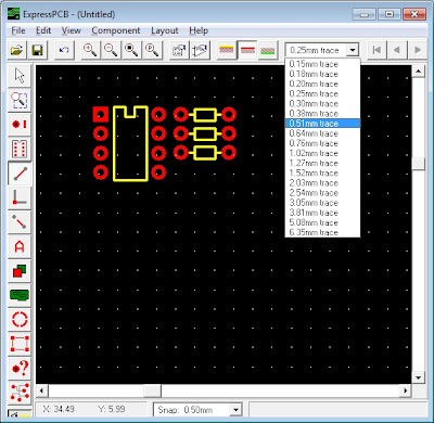
For home etching, we like to use big fat 0.5mm traces. Although we use a laminator for our projects, which does allow smaller/thinner traces to be used (we've successfully gone down to 0.2mm before now) we appreciate that not everyone has access to such hardware, and may be using more crude methods of transferring toner to copper (e.g. a household iron). Because of this, we found 0.5mm traces give the best results for anyone wanting to follow our board layout designs.


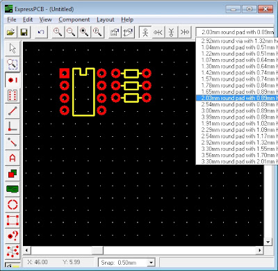
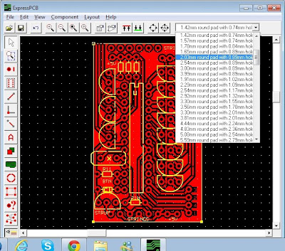
Because we do a lot of hand-drilling and sometimes even use a Dremel with bendy-attachment, we need quite chunky pads too (to allow a little bit of leeway if the drill is not perfectly centred). We've found that a 2.03mm pad with 0.89mm hole is ideal for us (and most other people) when using a standard 1mm drill bit


One last thing - ExpressPCB doesn't have an auto-route option.
Some people find this a problem - we've never bothered with it anyway (when we used autoroute in Eagle, we found we had to amend the final layout that it generated to make best use of the board space, so figured we'd be as well doing the board layout by hand). For home etching, we try to cram all our components together as tightly as possible - some people like to space things out: it's all about personal preference!
Here are a few common tricks you can use to help with board layout;


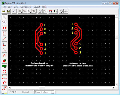
If you need to connect two sets of pads, keeping the numbering the same, but without regard for orientation (which way up the pads go) you can use simple "C-shaped" traces - each trace passes around the outside of the previous one. The pad numbering keeps the original order, but the final set of pads are "upside-down".
If you need to keep all pads in the correct sequence AND the right-way-up, use "S-shaped" traces. This connects, for example, the right-hand side of one pad to the left-hand side of another, but ensures that the resulting pads are laid out in exactly the same way as the originals.

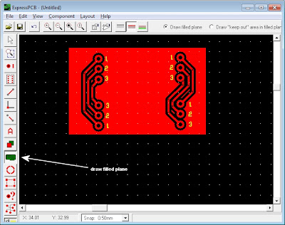
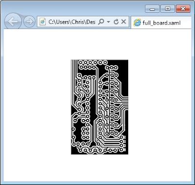
Before printing your PCB layout, create a filled plane to fill in the gaps between traces. If you just print out your copper traces, your Ferric Chloride will have a lot of work to do, removing all the material between traces. This means etching takes ages and also saturates the FeCl much more quickly than is necessary (once Ferric Chloride has etched a lot of copper away, it becomes weaker and weaker, taking more time to etch each subsequent board)

Note anything on the silkscreen/yellow layer will not get printed in the final design - so overlapping things on different layers is quite acceptable

Select the filled plane tool and draw a rectangle over the entire PCB layout.
Right-click to stop drawing the plane and your board should appear something like the image above.
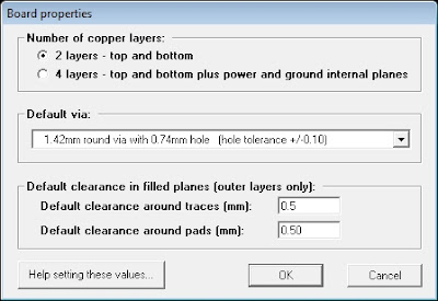
Change the board properties (menu Layout -> Board properties) and set the clearance around holes to 0.5mm to match the size of your traces.


The final printed design will have nice clear traces and big fat chunky pads which are easier to solder onto. Even if you're using a household iron to transfer the toner from the press-n-peel onto the copper board, the relatively thick traces and spacing between them should allow you to get away with a little movement during ironing (always a problem, and can cause smudged and broken traces when thinner lines are used).

When you transfer the image onto the copper board, it will, naturally be reversed. For example, pin1 on all your microchips is suddenly on the top-right hand corner, not the top-left. Don't panic - this isn't a mistake! That's exactly what you want, because the PCB image is on the bottom of your board. If you turn it over and place the components on the top (non-copper) side of the board, you should find that all the pads line up with the components perfectly (pin1 on the top side of the board is on the top-left, but turn the board over and it magically appears on the top-right side of a set of pins - because you're looking at the bottom of the chip, not the top).

Why use ExpressPCB?
It's free.
It's easy.
You can create drill files from it!

Creating drill files from ExpressPCB

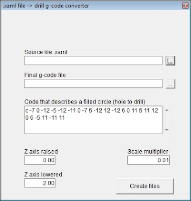
Here's a simple VB app that will parse an xaml file generated from an ExpressPCB PDF and plot the points for drilling in a separate file, and a g-code.
That's sound like more than it is, so let's look at what's involved:

Firstly, create your schematic and PCB layout in ExpressPCB. When placing pads, use pads with 2.03mm size and 0.89mm hole:


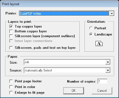
Print the top copper layer to a PDF file using CutePDF


Open the PDF file in Inkscape and save as .xaml
The .xaml file should open with later versions of Internet Explorer (amongst others) so you can check the conversion worked properly. Open the file in Notepad to see all the complex XML shape descriptions.


Now start up the VB app and provide it with the path to the .xaml file


There are a few parameters to mess about with here. The main one is the code that describes a circle. If you've used 2.03mm pads with 0.89mm holes, this should be c -7 0 -12 -5 -12 -11 0 -7 5 -12 12 -12 6 0 11 5 11 12 0 6 -5 11 -11 11. You should see this set of commands repeated throughout the .xaml file, each time preceeded by [mX Y] type commands. If you've used different pad sizes, look for something similar - a repeating set of draw commands at different positions, with a fill colour of #FFFFFFFF (the [mX Y] commands are movement commands, the fill colour is white: basically we're looking for the repeating white circles that make up the centre of all the pads).

At the minute, we're not sure what units the .xaml file uses compared to our CNC machine - it will take a bit of messing about to get this right, so there's a scale multiplier parameter. As the app finds all the drill holes, it applies this multiplier, to convert from screen units/co-ordinates to whatever units the CNC machine uses. The final parameters to set at the Z-axis movement axis. The app will create some G-Code which can be loaded straight into the CNC controller software (we use Mach3 but may change once the demo version runs out!). Depending on whether the machine is set up to use inches, mm, or some other unit, this value may need to be changed - it defines the start (retracted) and end (plunged) position of the Dremel for drilling.

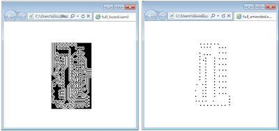
Pressing the "create files" button generates two files - one an amended .xaml file, so you can see a preview of the drill pattern generated. Load this into Internet Explorer (or some other software that lets you view .xaml) so see the final output.

The original and amended .xaml files showing drill hole positioning

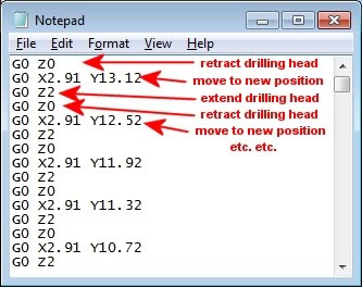
The VB app also creates a CNC-ready G-Code file with the points plotted, complete with "move-to" commands and "extend/retract drill head" commands.


Load the G-Code into the CNC controlling software and let it go!

Download the VB app here

Friday, 17 June 2011

Building a drilling milling machine

With the arrival of our CNC machine, all kinds of ideas starting springing to mind. But the idea behind getting a machine like this was to help speed up the production of PCBs - to easily create kits of components for workshops, like those run by BuildBrighton, or even to produce products for an online shop or to sell on eBay.

So that's where we're starting - to get the CNC machine to drill a series of holes that match up with a PCB circuit/design.

Following Tom's excellent research into g-code files, we're pretty confident that we can get the CNC to move to specific points above a sheet of copper-clad board, and activate the z-axis (up-and-down axis) to get it to thrust a Dremmel drill into the board. The most challenging part is to create the g-code to begin with!

So far, we've resisted all attempts to learn Eagle for designing and producing PCBs. But it looked like this was on the cards, since it already includes export options for drilling and milling PCBs. The only trouble with Eagle is, well, it's just not very nice. The software we use for schematic design and PCB layout is the excellent (and free) ExpressPCB.


It's just easier and all round nicer to work with - no confusing menus, sub-menus, things hidden inside other windows and so on. It has a really neat library of existing components, and if you can't find what you're looking for, creating your own is a doddle. Because we do a lot of home-etching, you can make big fat pads and traces really easily, and the final boards produced are easy to solder and work with. Eagle, on the other hand, was just confusing and produced boards with nasty lozenge-shaped pads and thin traces that were easily broken during etching.
The problem with ExpressPCB is that although the software is free, it's provided by a fab-shop who want you to send your designs to them for manufacture. As a result, there are no export options supported.

To date, we've always printed a PCB layout either straight to the printer (where the press-n-peel is already loaded and ready to do) or - using CutePDF - to a PDF file for editing.

Inkscape is a great program for editing graphics-heavy PDF files. So naturally we loaded our PCB into Inkscape and choose the "ungroup" command to break the board up into lots of lines and circles.
Then we selected the (black) centre circles found at the centre of each pad and copied them all to the clipboard. By creating a new image and pasting the copied shapes into the top-left hand corner, suddenly we had the basis for our drill file:


From within Inkscape we saved this new image as an .xaml file


This created an XML document, filled with plot and curve commands.
The curve/shape commands are of little consequence to us, but the plotting commands are just what we're after:


<?xml version="1.0" encoding="UTF-8"?>

<Canvas xmlns="http://schemas.microsoft.com/winfx/2006/xaml/presentation" Name="svg5395" Width="744" Height="1052"><Canvas.Resources/><Canvas Name="layer1"><Path xmlns:x="http://schemas.microsoft.com/winfx/2006/xaml" Name="path4253" Fill="#FF000000" Data="m 44.142826 61.717113 c 0 -1.05 -0.75 -1.8 -1.65 -1.8 -1.05 0 -1.8 0.75 -1.8 1.8 0 0.9 0.75 1.65 1.8 1.65 0.9 0 1.65 -0.75 1.65 -1.65"/><Path xmlns:x="http://schemas.microsoft.com/winfx/2006/xaml" Name="path4255" Fill="#FF000000" Data="m 44.142826 70.717113 c 0 -1.05 -0.75 -1.8 -1.65 -1.8 -1.05 0 -1.8 0.75 -1.8 1.8 0 0.9 0.75 1.65 1.8 1.65 0.9 0 1.65 -0.75 1.65 -1.65"/><Path xmlns:x="http://schemas.microsoft.com/winfx/2006/xaml" Name="path4257" Fill="#FF000000" Data="m 44.142826 79.717113 c 0 -1.05 -0.75 -1.8 -1.65 -1.8 -1.05 0 -1.8 0.75 -1.8 1.8 0 0.9 0.75 1.65 1.8 1.65 0.9 0 1.65 -0.75 1.65 -1.65"/><Path xmlns:x="http://schemas.microsoft.com/winfx/2006/xaml" Name="path4259" Fill="#FF000000" Data="m 44.142826 88.717113 c 0 -1.05 -0.75 -1.8 -1.65 -1.8 -1.05 0 -1.8 0.75 -1.8 1.8 0 0.9 0.75 1.65 1.8 1.65 0.9 0 1.65 -0.75 1.65 -1.65"/>


As you can see, every hole drawn in the .xaml file begins the Data tag with "m" followed by two digits. This is the "move" command. The digits that follow are the curve commands to draw a filled circle. We're not bothered about that - but what is of interest is the co-ordinates of the m command (i.e. where the hole is placed).

In fact, because every single hole on the board is drawn by the same filled circle shape, it should be possible to simplify this process in future. If we save the original PCB as .xaml (without first selecting all the hole points and copying them to a new image file) we should be able to pick out the drill holes, even from a complex PCB image.
As you can see from the .xaml example above, every hole has a move command, co-ordinates to place it, then exactly the same sequence of drawing commands - "c 0 -1.05 -0.75 -1.8 -1.65 -1.8 -1.05 0 -1.8 0.75 -1.8 1.8 0 0.9 0.75 1.65 1.8 1.65 0.9 0 1.65 -0.75 1.65 -1.65"

So in theory we should be able to parse the original PCB image file, even with all the traces and filled plane backgrounds and everything else, and just look for any shapes that include "c 0 -1.05 -0.75 -1.8 -1.65 -1.8 -1.05 0 -1.8 0.75 -1.8 1.8 0 0.9 0.75 1.65 1.8 1.65 0.9 0 1.65 -0.75 1.65 -1.65" in the Data tag. Any shape with this data in it we can say is a black filled circle (a 1mm hole that needs drilling) so our parser can strip out the co-ordinates from the "m" command. All other shapes can be ignored.

Results of a test app will be posted here soon.
If all goes to plan, maybe we won't have to shell out on an Eagle licence that we didn't really want in the first place.....

And now for something completely different....

As is becoming customary with this blog, just as one thing really starts getting going, another thing comes along and knocks it into a cocked hat. The same thing happened again this week. Only the thing that came along was pretty impressive and deserved some real attention.


It was a CNC Machine!

Yay! CNCs are great. They can cut shapes out of all kinds of materials. Laser cutters are great too (we have one at BuildBrighton) but they're limited to relatively thin material (acrylic, sheet mdf, thin plywood) and can't cut anything metallic. So for making enclosures, shapes, plastic objects and so on, a laser cutter is a pretty cool tool. But etching and drilling PCBs is where they fall short.

A CNC router, however, can do all the stuff of a laser AND drill PCBs. Ok, the cutting head is quite a bit fatter than a pin-point laser, so shapes aren't as intricate, but did I mention that it can drill PCBs? That's what we found so exciting about having a massive wooden crate arrive last night with said CNC machine inside it.

After it was unpacked, assembled and gingerly switched on, the big sturdy metal gantry sat there, filled with potential energy. When the control panel was switched on, the stepper motors on each axis suddenly had resistance and the rods were difficult to turn by hand (when switched off, you can easily move the gantry by turning the rods manually).
The motor control gear looked somewhat homemade, but very robust - the control board had a great big fan on it, and plenty of heatsinks all over the place! The CNC came with a genuine copy of RoutOutCNC and a few sheets of paper with some handwritten notes. We fired up the software but with no idea how to use it (and no inclination to read the instructions!) we quickly got bored with just pressing buttons and getting no response from the machine.

The control gear lives in it's own enclosure, unlike a lot of cheaper CNCs which have it under the machine, where it can clog up with swarf and cutting debris

Laser Steve from botbuilder had previous experience of CNC machines, having built one of his own, and suggested we install Mach3 and use that to control the machine. We duly got the demo version of the app and tried it out. With partial success, we managed to jog the gantry to the left, by pressing keys on the PC keyboard. With the gantry at it's limits, we had to find a way of getting it to return again! This meant poking about in the Mach3 config screens - specifically the Ports and Pins section, making sure that the stepper motors used to drive the X,Y and Z axis were connected to the appropriate pins on the parallel port (or, rather, we told the software which pins on the port each axis stepper motor was wired up to!)

Yes, the Mach3 interface is seriously horrible!

Luckily Tom from almostobsolete.net was at BuildBrighton last night and he's spent some time playing about with stepper motors too. It didn't take long for him to have the machine jogging backwards and forwards along all three axis.

Something that did cause a problem was after a few seconds of movement, the stepper motor(s) started making a "slipping" sound - they would spin the leadscrews for a short while and then make a nasty screeching sound and the motors would stop spinning. At first we put this down to the couplers (the bit of nylon connecting the stepper motor to the leadscrew) slipping, but we soon discovered that it was the motor itself that had stopped spinning.
By slowing down the ramp up and down times in Mach3, it seemed that the software was trying to control the motors too quickly - while they were ramping up, they span perfectly well, until they hit a point where they would slip and screech. By reducing the spin speed of the motors down from 120 inch/min to about 20 inch/min, this rather distracting noise was eliminated.
(this might be a bit overkill and too slow, and we've yet to discover where the speed issue lies - it might be the old PC we used as a controller can't send the data quickly enough, it might be that the driver board can't handle the data arriving any quicker than 20"/min or it might be the stepper motors themselves: we don't know enough about any of the hardware to say what the problem is just yet!)

But with the ports & pins settings adjusted and the motor max speeds reduced, the CNC finally came to life and could be controlled properly.

We tested it be loading some g-code for simple shapes - starting with a square, which we then amended (by hand using Notepad) to draw a triangle, and finally a circle. Tom even went so far as to create his own g-code to draw arcs and connect points with lines and paths!

Drawing PacMan with a marker pen instead of a router installed. We figured that if we could change the paper quickly enough between frames we could even play a game ;-)

We've got great plans for this machine and hope to be turning out machined shapes and components and PCBs in the very near future.....

Wednesday, 15 June 2011

Creating your own text-to-web interface


To allow readers to re-create our remote switching unit we've set up an SMS-to-web gateway that anyone can use to try the ideas out.

We're using a shared short code, 88802 and the keyword 2mbed.
We've set up our interface to strip out the second word in a message and use this as a second keyword to allow anyone to use the same system we do for dealing with messages, but without the cost of purchasing and maintaining your own short code number.

To try the service out, visit http://www.nerdclub.co.uk/mbed

Simply create your account and set up your own keyword on this server to be able to post messages to the database. Write a text message, beginning with 2mbed [space] your_keyword followed by the rest of the message. To access your messages, log in or call the webpage
http://www.nerdclub.co.uk/mbed/messages.asp?keyword=your_keyword&password=your_password

Friday, 10 June 2011

What's all this gibberish about?

After a few readers asked why I wanted to read a webpage using my mBed dev board, which appeared to contain nothing but gibberish, it's probably time for a fuller explanation.

The idea was, of course, to get a simple prototype working, then post a series of blog entries detailing how we got it to work. But since we're not at that stage yet, and recent posts have stirred interest, here's what we're trying to do:

The mBed will form the heart of a switching unit.
We've already built something similar, years ago - a PIC based board which can activate (and de-activate) a number of relays. The relays provide isolation to a 240V mains supply - so we can use a microcontroller to switch things off and on around the house.

With the mBed we had hoped to take this a stage further.
The problem with the PIC-based approach was that it was a USB device, and so needed to be connected to a PC all the time. By using the ethernet support on the mBed, we could do away with the PC altogether - the microcontroller could talk to the web server directly and receive messages. (yes, this could be achieved with a bluetooth-to-serial type adapter, to talk to the router via wi-fi and relay messages back to the MCU over serial, but this project was originally to help us learn to use ethernet for something useful!)

Anyway, here's where we're up to:
We want to be able to send messages over the internet, to get the switching unit to turn things on and off. In fact, we wanted to take this idea further and to send text messages to our little switching unit. The final aim - and proof that it works - is to be able to send a text message on the journey home from one of our BuildBrighton meetings, and have the kettle/coffee pot switch on, so there's a nice hot cup of coffee waiting when we get in!

In the fullness of time (and when we've got two-way messaging working, so the switching unit can report back it's status) this sort of thing could actually be useful for vulnerable or disabled people, to help support them in their homes....

Anyway, while we're still trying to get the microcontroller to talk to the router, we ploughed on ahead to set up the text messaging side of the project. By using a text-to-web gateway, we can provide two means of accessing/controlling our switching unit while away from home. As before, other ways of achieving the same result exist (get the microcontroller to talk to a SIM card and send text messages directly to the unit) but we decided on the text-to-web approach and are determined to stick with it!

To send text messages to any internet connected device, we:

1) bought a keyword for a shared shortcode from textmarketer.co.uk
This costs about £6/month (because we picked the cheapest keyword they did)
2) created a script on our web server to capture messages and store them in a database
3) told the textmarketer.co.uk interface about the script

So what happens now is that whenever a message beginning with the keyword 2MBED is sent to 88802, it is forwarded (by the textmarketer server) to our web script which stores it in an online database (why the awkward keyword 2mbed? Keywords that begin with numbers cost £6/month, keywords beginning with letters cost £12/month - this is for a proof of concept, so we didn't want to go splashing the cash!).

We then built a separate web page which reads this database and displays any captured messages, using special characters as delimiters so we can break the data up for parsing at a later date. It is this web page that we want the mBed device to poll, and act on any messages received


As you can see from this screenshot, we've already captured a few text messages. The web output includes a number of messages in the form:

GUID (32-character globally unique id to identify the message)
Date message was received (in YYYY-MM-DD-hh-mm format)
Phone number the message was sent from (obscured for privacy reasons!)
The actual message (everything following 2MBED in the SMS body)

Each of these bits of data is stored separately in the database (the textmarketer web API also captures the network used to send the message if this is of any use). We write this data out to a web page, using the carat (^) symbol to denote the end of a field, and the hash character (#) to denote the end of an SMS message.

That's it really. Quite simple.
We've also added some extra trickery into the web script to allow you to try it out, without the need to pay for your own short code. Simply visit http://www.nerdclub.co.uk/mbed and follow the instructions to create your own keyword for a text-to-web interface.

Note: sending text messages to shortcode 88802 only works from within the UK

Never working is better than working sometimes

After trawling the mBed forum and trying out lots of different HTTP client type examples, I was shocked earlier today to actually see some HTML appear in a terminal window. Success!

The mBed successfully talked to the router, got an IP address via DHCP and made a request to my own server (I've set up a web page to broadcast messages when a username/password combination is sent).

Unlike previous attempts, I used the Twitter example which uses HTTP POST instead of HTTP GET to retrieve a response from a web server (it actually posts data to the server too, but I'm not interested in that side of things yet).


I was utterly amazed to see a response from the server appear in the terminal window. Finally, something was working and I could concentrate on building my web-enabled device. True, it was still a niggling concern that previous examples hadn't worked, but by now I just wanted a working solution (see how this whole library-based approach to development just makes you abandon understanding for the sake of getting something to work?!)

I was so thrilled, I wanted to see my web page contents appear again, so I pressed the reset button on the board and waited for it to get the data again.
Nothing.

It was assigned an IP address, then just sat there.
Very much like the previous attempts - it got to the HTTP POST command and just locked up!

I reset the board again.
Nothing.

Then again.


This time, some HTML appeared in the terminal window.
What the......
Exactly the same code running on exactly the same hardware, calling exactly the same web page (nothing changes between attempts) sometimes works and sometimes doesn't. A more frustrating scenario I can't imagine just at this time!

After repeating the experiment, I now have a sort-of-working HTTP client which can return data from a website, but only once every six or seven attempts.
Straight away, I thought hardware - dodgy soldering and loose wires - after all, if the software/firmware doesn't change between it working and not working, it must be something else.

I replaced my home-made RJ45 socket (which still works with other development boards, so I'm convinced it's not the problem, but just to be sure) with a pre-built breakout board, with all the connectors in place.


The result was the same. Resetting the device (or removing power from it completely) resulted in more locking up and occasionally a response written to screen.
All in all, a really frustrating week - I feel it would have been better spent building an ethernet device to connect to a PIC-based project myself! At least then, when it didn't work properly, I'd at least have some understanding about what was going on and maybe even why it wasn't working.

I've never been a fan of plug-n-play type development, as it discourages full understanding. And my experiences with the mBed development system haven't done much to change that view just yet!

First mBed development

As a PIC developer, and member of BuildBrighton, I often get a bit of stick from the others who are avid Arduino fans. The very reason most people love Arduino is mostly the reason why I don't get along with it - it's not the C-based language or abstraction (both of which I already use quite extensively when writing Actionscript for Flash) but what really bothers me is the over-reliance on libraries.

When I write PIC code, I tend to pore over reams and reams of boring (and confusing) datasheets, try to understand what is going on inside that little black box of magic, and write code to make it do exactly what I want.

Arduino has become successful because of the massive community of people who write code for it and post the results as "libraries" that other users can simply download and include in their projects. That's great provided the code is well written in the first place. There are a lot of people successfully using Arduino for their projects who don't really understand a single line of code! But by plugging together a few different libraries, you can get a working prototype up and running fairly quickly.

Despite my prejudices towards library-based coding, the lure of an ARM7 processor with built-in ethernet was just too much! The mBed development kit I was sent seems perfect for building quick and easy prototypes with very little knowledge of the underlying hardware. I've never built an ethernet stack, nor would I know where to start, but the mBed website provides a number of libraries and examples showing how to build a working HTTP client (some code that runs on the microcontroller and retrieves web pages from a URL is all I was after!)

Now the gripe - it's been over a week since this little thing arrived through my letterbox and I set to working immediately on ideas to try out it's hardware features. Since I'd already got access to most of it's peripherals through the PIC 18F series, I concentrated on the one thing it trumped a PIC with - ethernet support.

Yet nearly a week later, and despite the supposedly simple copy-and-paste approach to coding with the mBed system, I've yet to make a working HTTP client!

I have the 2368 series board (which has an 60Mhz ARM7 onboard, later versions such as the 1768 have a Cortex-M3 CPU running at 100Mhz) but not one of the HTTP client examples from the mBed website works.
Some of the other guys at BuildBrighton use the 1768 type mBed kits and the code works first time for them - but on my board, it just keeps locking up. (Some of the other guys at BuildBrighton just laugh and say I need to get an Arduino with an ethernet shield, but pfffft.)

I've used the same RJ45 sockets as the others, tried to communicate over the same networks, connecting to the same routers/hubs and while their boards all return HTML data almost instantly, whenever my board hits a HTTP GET type command, it just locks up!

And so the point of this grumble - it's still relatively early days for the mBed system. Which means the community is still pretty small - and the support just isn't there yet. I've been posting to forums asking for assistance, but haven't yet had any reply that has proved useful (whenever anyone at the Skiff has an Arduino-type problem, they can post a question and expect half a dozen answers within a few hours!). And the major problem - for me at least - is that I have no idea of what is going on inside those libraries to get to the bottom of why it's not working: which is mostly due to the way a library-based development system works. With a PIC, you work at almost byte and bit level - you can see every register and find out what is going on at the tiniest level. With the mBed system (and similarly, Arduino) all the clever, tricky, brain-hurting stuff is hidden away inside a few APIs supposedly making these things really easy to work with. Which is fine, when the libraries are well written and work all the time. But when they don't and there's no support, there's nowhere left to turn. Except, perhaps, back to my PICs.....

Thursday, 2 June 2011

Farnell/element14 supporting new development

As a member of BuildBrighton, I've been taking part in some exciting competitions run by Farnell/element14. I've been a long-time customer of Farnell and bought most of my equipment through them (long gone are the days when you could pop into a local Maplin store and speak with someone knowledgeable about components and get help with your homebrew project!). They've always offered excellent service, a really comprehensive catalogue of components, and next day delivery even if your order doesn't go in until late into the evening!


I know a lot of people use RS Components and Rapid and even I still scour eBay for job-lot bargains, but mostly, when it comes to sourcing electronics components, there's only one website on my Google Chrome regularly visited list - and it's Farnell. In short, I think Farnell are great!

And now there's even more reason to rave about Farnell - because their recently re-branded element14 department has been running a number of projects to encourage interaction with the developer community. Not only did they organise the Worldwide HackerSpace Challenge, but they also gave away free cash (yes, real, genuine cash to spend anywhere, not just on their webstore) to provide the community maker groups with a budget to develop their own ideas!

As well as this, Farnell are actively encouraging developers to submit their ideas and helping by providing equipment and development kits: all completely free of charge! There are no caveats or conditions - if one of their guys likes what you're doing, look out for an email asking what you'd like to play with from their massive catalogue of components and look out for some freebies in the post!

We got an mBed development kit completely free. In fact we were offered anything from the Farnell products catalogue to try out and review, but we headed straight for the NXP storefront (http://uk.farnell.com/nxp) to check out the latest ARM7 development kits - although PICs are great, we're looking to step up to something bigger and beefier soon, and the NXP mBed system looks like a nice easy introduction to ARM7.

We're kicking a few ideas around to see what we can do with it, but already have a steer on what we can use it for. More details will be posted here as they're finalised.....

Wednesday, 1 June 2011

mBedded is embedded

A lovely surprise this morning here at Nerd Towers - after an afternoon on the beach, I returned home to find an evaluation kit sitting on the doormat, from the guys at Farnell.
After publishing a number of project ideas at BuildBrighton, and posting some ideas on an earlier blog, Geektar (a guitar for geeks), we were thrilled to be invited to evaluate the mBed development board and to "blog" about the findings here.

So the first thing to do was to have a look what we'd been sent.
The contents seemed a little sparse - a dev board, a usb cable, a plastic credit card showing the pinout and a single sheet of A5 basically saying "go to the website and learn more"


In fact, the credit card proved to be more interesting than we first thought.
It shows all the cool stuff that the processor supports - and it's a pretty impressive list of stuff! The mBed system is based on an ARM7 processor and it has some pretty cool features. It's a 40-pin microcontroller (similar to the PIC18F4550) and has lots of hardware features you'd expect to find on a higher-end 'controller:

2 x hardware SPI interfaces
2 x hardware serial/USART interfaces
2 x hardware I2C interfaces
6 x analogue-to-digital input pins
1 x digital-to-analogue output pin
6 x hardware PWM pins
USB support
CAN interface (home automation CANBUS?)
1 x ethernet/networking interface

Most of these functions are either available on the PIC18F series of chips, or can be recreated in software (see our 20-channel servo controller project for examples of how multiple PWM output pins can be generated using software) but being a 32-bit processor and supporting much faster speeds (PIC 18F runs at up to 48Mhz, ARM7 up to 72Mhz) the mBed controller is perfect for processor intensive tasks like driving displays, multi-processing and so on.


But what sets this chip apart from other chips we've worked with is the exciting introduction of onboard ethernet. Until now, most of our microcontroller projects have been USB-based, requiring a host PC. Most of the time, this is more than adequate, as the functionality of the device can be greatly enhanced through the use of some custom-built software.

But the mBed dev board suddenly makes "real" embedded systems a possibility:
the introduction of the ethernet interface means we can create devices which talk to our home internet connection and control (or be controlled by) commands send so/from the 'net.

The mBed system couldn't be easier to use: the device itself appears, when connected to a PC, as a removable drive. Code is compiled into .bin files and you don't need a programmer or any special hardware to "burn code" - just copy and paste the .bin file to the device, press the reset button and the mBed device restarts, running your code! It's that easy!

The examples on the mBed website are pretty impressive too - it uses a number of pre-built libraries, similar to the approach used by Arduino, and abstracts all the complicated low-level stuff, allowing you to concentrate on just getting your stuff working. Code is written using an online editor and saved to the "cloud", so it's always accessible wherever you are. This makes it ideal for cross-platform development and sharing code, whether you're on Windows, Linux or Mac. There's no software to install or complicated folder paths to set up. In fact, to re-program the device you simply plug it in and download a new file to the removable device.


One of the first ethernet examples on the mBed website shows how an RFID tag can generate tweets, to show who has arrived over the course of the day. As we're looking to make a stand-alone device that will communicate over the internet (without the need for a host controller) these examples will form the basis of most of our learning in the coming days.....