Saturday, 29 July 2017

Hall sensor array quick post

Just a quick post in response to a couple of questions we've been getting for a schematic for a hall sensor array, being driven directly off the Arduino i/o pins.


If you place your A3144 hall sensors in a grid pattern, with the "flat" part of the sensor facing down (with the slightly bevelled face pointing upwards) then all of the centre pins should be connected together (a common ground).

Each of the left-hand pins should be connected horizontally to the sensors immediately left/right of them. Each of the right hand pins should be connected vertically to the sensors immediately above/below them.

The left-hand pins are the power supply for the sensors.
The right hand pins are the open-drain collectors (outputs) of the sensors.

We try to put the output pins (from the sensors) on our Arduino D2-D9 pins and make them inputs with interal pullups. We try to connect the output pins to power the sensors onto the Arduino D10-D17 pins and make them outputs, because D13 usually has an LED connected to it - you can still power a hall sensor from this pin, but using D13 as an input can be problematic.

Hope this clears a few questions up!

Friday, 23 June 2017

Back in the saddle

Well it's been a funny couple of months.
Firstly all kinds of personal and family issues meant I was travelling the country and not really spending much time at home nor in the workshop bungalow.

Then along came a General Election.
I've always taken an interest in politics, and always been a firm believer in engaging with people - whatever their political persuasion - to get people discussing policies and what parties actually do, rather than the usual X-Factor style personality vote that many elections have become.

So when the UK elections threw up a hung Parliament, the conversation didn't just stop. In fact, at the time of writing, things haven't exactly been sorted out yet. The Tories have yet to confirm a deal with the DUP to keep hold of power and there could be another General Election any time soon (although its unlikely to be before the upcoming summer recess).

On top of this, work still needs to get done to pay the bills.
So there's not been much time for messing about in the bungalow, making stuff with the 3d printer or cutting stuff out with the laser cutter.

But that's all about to change.
Enough with politics. Enough with being angry.
It's time to get making stuff again!

Monday, 15 May 2017

Light up guitar demonstration

So the light-up guitar is complete and ready to try out.


The chords and scales mode works really well.
And playing blues licks (with the blues scale selected) is great fun. As many guitarists already know, when playing a 12-bar pattern, it's quite common to play a major pentatonic melody over the one (I) chord, and a minor pentatonic melody over the four (IV) and five (V) chords. This is what gives the blues its distinctive "blues-y" sound (for you music theorists, it's the clash of a minor third over a major triad with an added flat 7th that really makes the blues sound like the blues, but the principle is the same).


By just noodling around playing notes from a scale you can get a nice blues-y guitar sound; coupled with a bit of rhythm, there's a very real danger of it actually sounding melodic!


Flicking the major/minor switch makes playing/finding chord tones really easy. Root notes are always in red. Thirds are in pale blue. When in "major" mode, the fourth degree of the scale is bright purple. So find a purple note, and the major third is immediately behind it. Slide into (or hammer on to) that note and you instantly get that blues sound.

My own personal arsenal of blues licks is limited to about three licks. But even then, playing those couple of licks with the fretboard lit up makes understanding how and why they work much easier. You can actually see when you're bouncing around the major/minor third, you can see as well as hear the effect of sliding or bending to a flat seventh, you can see why a particular lick sounds good over the four chord (because it has a fourth of the scale in it) and doesn't always fit well over the five chord.

From a learning point of view, it's a real success.
From a guitar point of view.... well, not so much.

For a start, I didn't do a very good job of clamping the fingerboard absolutely flat when gluing it to the neck. In fact, there's a tiny bit of a back-bow in the neck once it's on the guitar.
Which means I've had to really jack up the bridge and put on some super-heavy gauge strings, to try to get the neck to bow "forwards" a little bit.


with the straight edge sitting on the neck, you can see a slight gap between the ruler edge and the frets on the left, furthest away from the body. Unfortunately, this means the neck has a slight back-bow at around the fifth fret, causing lower notes to "fret out" and buzz really badly.

So although the backbow can (just about) be compensated for, it's at the cost of really heavy strings (13s on the highest E). Which, as you can imagine, makes playing blues-y licks, with lots of vibrato and string bending really tricky.

There's also a dodgy earth problem that needs finding and addressing.
It's barely noticeable when using a clean-tone amp. But add in a bit of crunch (I use the overdrive switch on my amp but the same effect happens with any high-gain effect pedal with any  kind of treble boost) and suddenly you can hear the additional electronics in the guitar signal.


When using the menu, there are audible clicks in the audio signal. But the best is when the LEDs light up. The PWM signal driving the LEDs sounds like someone blowing into an open-ended piece of drainpipe. Very peculiar!

So there we have it - a working light-up guitar. Of sorts.
It lights up. It makes finding and playing scales easy.
But it's an absolute pain to actually play.

Keith will just have to hang on a little bit longer - I'm already started on a new guitar neck which I'll make sure is created flat and not bowed. And maybe we'll try moving the electronics out of the guitar body and hooking up to a separate, dedicated box of tricks, well away from the pickups and anything else that might affect the audio signal....


Monday, 8 May 2017

Thwarted at the last!

After swapping out a couple of dodgy Nokia LCDs and some last-minute rewiring (to enable a 2000mAh lipo battery to power the whole thing as well as be charged from a regular phone charger) the back of our guitar scratchplate was looking a bit of a mess (ok, Keith, your guitar scratchplate)

We went from this....

....to this!


There's a lot to cram in there.
And even after doing some extra routing on the body


and tidying up the wiring (a little bit)


it finally came to assembling everything for the final dry fit.
Sadly, it didn't quite fit!


And it's a little bit late in the day to be running the router and hacking out lumps of wood from the body. So that'll have to wait 'til the morning. In the meantime, here's a final test, to make sure that the new wiring still works properly:


Everything works well;
The phone jack acts as a data connection for both midi and bluetooth data (not demonstrated in this video) as well as a charging point. The power switch allows you to flip between mains powered (the battery charges while connected) or battery powered. The second tone control has sneakily been replaced with a rotary encoder to navigate the menu. The major/minor flip switch lets you quickly and easily change between major and minor scales, while keeping the root notes highlighted in the same colour (red). All in all, it's pretty exciting.

Just a shame there was no time to get the router out and finish it off fully!

Thursday, 4 May 2017

Unity and TextMeshPro

I guess, since Unity "bought up" TextMeshPro and made it available for free with version 5.5 of Unity back in February, I'm probably one of the last to jump on board and give it a go.

Between messing about with Arduino, guitars and hall sensors, I've been playing about with Unity a bit too. I tried getting away from the whole "create the next awesome 3d blockbuster" and am looking to create simple, mobile-friendly games that should provide 10-30 minutes playtime. A bit like the old ZX Spectrum games of yesteryear (though I shudder to think how many hours I spent trying to get Mr Head and Mr Heels to work together properly in 1986).

Anyway, a simple 2D turn-based strategy game is currently in development (although it'll probably never be anything more than a vehicle for trying out different coding techniques,so don't expect a release date any time soon) and - like most game framework prototypes - is filled with coder art, empty graphics placeholders and lots of console debug messages.

As anyone who has worked with Steve will know, it's the graphics and look-and-feel that can elevate something pretty mediocre into something amazing. And that's what happened last night, when I swapped out my simple Unity GUI Text for some TextMeshPro glyphs.

Here's an example. It's dynamic text.
At certain points in the turn-based game, your turn can be interrupted by your opponent (a classic example of this is when a player leaves a character on "overwatch" - meaning "if anything crosses your field of view, shoot at it immediately").

Whenever a player is interrupted, we wanted a nice big on-screen display to inform them of what was going on. A simple 72-point dynamic text box just didn't seem to cut it. But swap out the text object for a TextMeshPro mesh and suddenly things look a lot prettier, very quickly


Just simple stuff like putting a gradient on some text can make it look so much better than a simple flat font. And TextMeshPro lets you define up to four gradient points (to get that shiny metallic look on each letter if you like).

Also, when you scale a text object up in Unity (for example, to create a "bounce-up" effect) even TTF fonts become pixellated at larger sizes. No such problem with TextMeshPro!

It's such a massive improvement on the original UI Text, it's no wonder Unity bought it up and now offer it for free as a Unity Essential. It's a great asset and a quick and simple way of making even boring stuff look pretty onscreen!

Wednesday, 3 May 2017

Assembling the light-up guitar

Things have slowed down a little bit, as assembling the guitar has proved to be a little more difficult than designing the electronics and writing the firmware!


The first thing to  do was make a note of the existing connections - just in case anything accidentally gets snipped or un-soldered. Then we whipped the scratch plate off and set about it with a Dremel and a small routing bit to make a window for our LCD display.


That triple-layered plastic made a right mess! Copious amounts of hot glue ensures our screen shouldn't be going anywhere, any time soon.


We took out the second tone knob (the one that's almost always left fully dialled to ten) and replaced with a fixed-value resistor. After all, the tone knob on these cheap Strat copies doesn't boost any frequencies, it can only choke them. And what's a Strat if it's not got that bright, jangly sound? Why would you want to dial that down anyway? So off came the pot, to be replaced with a fixed 220k resistor. In it's place we fitted a rotary encoder.


After cutting down the shaft and putting the tone cap back on, you'd never even know it had been modified if you weren't looking closely! Also added a stereo jack socket which we'll use to connect to the power/ground/RX pins of the microcontroller to allow data to be pushed into it at a later date.


Now for a really important part - lining up the neck and bridge. On a previous build, we missed this step out; fixed the neck, drilled the holes for the bridge, installed the tremolo system and found that the bass strings were almost in the middle of the neck and the high treble strings were fretting out, as the high E string was barely on the neck!

No chance of that happening this time around - some lengths of cotton allowed us to see where the strings would end up, to ensure we got the bridge in the right position this time.


You can see where, under the scratchplate, we had to do some extra routing to create a cavity for the LCD screen and 3000mAh lipo battery. A quick test fit made sure that everything was going to fit inside the cavities when assembled.


The firmware isn't quite finished yet (need to add in a couple more fancy patterns and recreate our earlier volume meter effect) so we're not quite ready to close it up and fit the strings. But that time is coming. It's coming real soon......

Saturday, 29 April 2017

A quick thanks to Jason for the MIDI-in schematic (and opto-isolators)

If you're having trouble with your MIDI (as we were, trying to get our input working through an opto-isolator) there's only one person with the wealth of experience worth asking and that's Jason. He quickly identified that the random spare-part left-over opto-isolator we were trying to use for our MIDI-In simply wasn't up to the job.

Apparently there isn't a great range of opto-isolators to work from for handling MIDI. Most are simply used as switches. And while its' true that serial data is just flipping a switch really quickly, we need an opto-isolator that can switch on and off quickly enough to keep up with the data rate.

Jason kindly gave us a couple of 6N138 isolators and an updated schematic to work from.


The isolator neatly inverts the MIDI logic (in MIDI a zero is a high signal and a one is low) as well as holding the RX line high when idling - just how all good UART peripherals like it.

With this slight alteration we got our MIDI In working reliably - with the added bonus that we can now hook up and MIDI source, powered from anywhere; the isolator means there's no need for a common ground or similar reference. Which is just as well - to date we've tested our light-up guitar fretboard by loading MIDI files on the laptop and playing them through a usb-to-midi interface conntect to a second usb port. This means the serial port and the MIDI signal have both been generated from the same source.

But the ultimate test of our MIDI capabilities will be when we plug the guitar into a portable keyboard, press a key and see which of our frets lights up!

Friday, 28 April 2017

Displaying MIDI notes as fret positions

To convert scales and patterns into LED combinations we've made quite extensive use of spreadsheets. Boring old boxes of numbers have made displaying patterns of dots much easier.

The guitar fingerboard LEDs have been wired starting at fret 15, low string E, passing through each string of the 15th fret (E, A, G, D, B, E) then continuing with LED number six representing 14th fret low E, LED seven is the 14th fret A string and so on.

So we first drew up our patterns in a spreadsheet, coloured the boxes (to make them easier to identify) then transferred these patterns into byte arrays.


Anyone familiar with guitar scales might see the pentatonic minor box one starting with the A root note on the fifth fret in the image above.

After giving each note of the scale a "colour palette index", we stored each pair of strings in a single byte. So the low E string is the upper nibble of the first byte, the A string the lower nibble of the first byte, the D string is the upper nibble of the second byte and G is the lower nibble. The B string is the third byte upper nibble and lastly the high E string is represented by the lower nibble of the third byte.

So reading the scale chart from the bottom right corner, reading upwards, then from right to left, our fifteenth fret LED colour index values are 7(E), 2(A), 0(D), 0(G), 4(B), 7(e) (zero represents no dot to be displayed). The fourteenth colour index values are 0, 0, 5, 1, 0, 0.


You can see that by splitting each fret/string position into a single half-byte 0-F, when storing the values in hexadecimal, we can actually "see" the dots in the code. The first three byte values, for the six strings on the fifteenth fret are 0x72, 0x00, 0x47. The correlates directly with the dot patterns in the spreadsheet 7(E), 2(A), 0(D), 0(G), 4(B), 7(e)

Using a similar technique, we listed the note values of every fret position for every string.


Then after a quick Google look-up, recorded the MIDI note value for each note at each fret position, for each string. Recording the MIDI values in the same order we've wired the LEDs, our array of values begins 31, 36, 41, 46, 50, 55

These are the midi note values for G2, C3, F3, Bb3, D4, G4 which happen to be the notes on the guitar at the fifteenth fret.


Since the seven LED is at the low E string position on the 14th fret, our array of MID note positions continues 30, 35, 40, 45, 49, 54. We continue recording each note value in our MIDI array, all the way up from fret 15 to fret zero (open strings).

const byte midi_notes[] PROGMEM = {
  31,36,41,46,50,55,
  30,35,40,45,49,54,
  29,34,39,44,48,53,
  28,33,38,43,47,52,
  27,32,37,42,46,51,
  26,31,36,41,45,50,
  25,30,35,40,44,49,
  24,29,34,39,43,48,
  23,28,33,38,42,47,
  22,27,32,37,41,46,
  21,26,31,36,40,45,
  20,25,30,35,39,44,
  19,24,29,34,38,43,
  18,23,28,33,37,42,
  17,22,27,32,36,41,
  16,21,26,31,35,40
};

Now when we receive a MIDI note value, we can loop through this array to work out which LED corresponds to that note and light it up (or, if it's a note off message, turn it off).

void addNoteToFretboard(byte note, int col_index){
  // loop through all the midi note values in the array
  // and wherever there's a match, light up that LED with
  // the appropriate colour index
  byte p;
  CRGB c = RGBColour(col_index);

  for(int i=0; i<96; i++){
    p = pgm_read_byte(&midi_notes[i]);  
    if(p==note){
      led[i] = c;
    }
  }
  FastLED.show();
}

(in the example above, we have a function into which we pass an index number and it returns a CRGB value for a specific colour)

When hooked up to a MIDI source, the result looks something like this:


That's the opening sequence to Metallica's Enter Sandman. If you already know how to play the song, you'll recognise the familiar patterns around the 5th, 6th and 7th frets. For some notes, more than one dot appears. That's because there's more than one place where you can fret the note. Matching colours mean "it's the same note" so you'll see a red dot appear at both the 6th fret low E string and 1st fret A string at the same time. You can choose whether to play the riff on the 6th/7th fret, or on the 1st and second - it's up to you!

At the minute there's no differentiation between channels - you need to turn channels on and off using your MIDI sequencer - so when we wound the song on a bit and played it complete with distorted guitar, bass notes and drums/hi-hat, it looked a little bit crazy!


However, as a performance piece, we think it looks pretty cool too!

Thursday, 27 April 2017

Messing about with MIDI and RealTerm vs Putty

While our guitar neck glue is going off, and since we've pretty much got most of the LED goodness working (that'll probably have to be demonstrated in a later post, once everything has been stuck together) we thought the intervening time could be spent adding some extra cool functionality to our light-up guitar.

To date it allows you to select pentatonic or diatonic scales in any key, include extra notes (such as the "blue note" and flatted/major thirds in the minor pentatonic, major fourths in the major pentatonic and so on). You can also have it display all the major C.A.G.E.D chord shapes in any key too (we really should have made a demo video before this post!)

EDIT: made a quick demo video. Here you go -


In "offline mode" you can display different scales and CAGED chord shapes in any key. A simple flick switch will allow you to quickly change between major and minor (for those pesky I-to-IV and IV chord changes in a 12-bar song!) And, of course, there are some fancy patterns just for show as well!

Now most guitarists who know how to play guitar recognise that it's not just a Guitar Hero clone - where frets light up and if you match them with your fingers, you'll play a tune. By lighting up a particular scale (and different target notes from that scale) you can improvise blues-based solos more easily just by wandering between the dots. But for anyone wanting to play along to their favourite song, we figured it'd be a massive amount of work creating some software that allows you to input tab in such a format that you can then send to the guitar to get the frets to light up.

So when MIDI was suggested, we figured.... hmmmm.
It's always tricky knowing which of a possible five places you should place a dot for a specific note on a guitar. But if we could take the incoming MIDI signal and simply light up all possible alternatives, it would leave the player to decide which fret they found most comfortable to reach for (instead of some crazy algorithm going rogue and forcing you to whizz up and down the guitar neck at lightning speed!)

So we needed to get to grips with handling MIDI in signals (not the infinitely easier generating MIDI out messages). The first thing was to hook up a usb-to-MIDI device so we had an independent way of generating MIDI messages.
Now MIDI uses inverted logic (zero is represented by a HIGH signal, a one is a LOW signal) but other than that, it's simply serial data sent at a funny baud rate. 31250 bps to be precise.

So we downloaded a free MIDI sequencer (Anvil Studio looks gnarly and draws slowly, but it can create, edit and play MIDI files to a MIDI device, so it was good enough for this test) and grabbed something a bit more sophisticated than our usual serial favourite Putty - a little program called RealTerm.

Putty is fine for sniffing data, but RealTerm makes playing with serial data a doddle. Not only can it display the raw incoming data, but it has a myriad of options for decoding it too. We went with hex[space] so that we could visualise the MIDI values in hex, instead of trying to decode non-printable ASCII characters (as Putty likes to do). It's much easier to see what a value like 0xB4 means than a checkerboard patterned glyph!


We hooked up our MIDI out to a socket and introduced an opto-isolator to both isolate and invert the MIDI signal from our usb-to-MIDI device. The circuit was something similar to this one (with a few resistor values changed to match values we had lying around)


The strange this is, we got no data from the circuit. Absolutely nothing.
After fiddling about for about an hour and getting nowhere, we took a bit of a risk. Since the MIDI signal was being generated by a laptop usb port, we figured it wouldn't be more than 5v. So we connected the MIDI out directly to our serial in.....
Instead of a puff of blue smoke, we got serial data appearing in RealTerm. Success! (although we did have to invert the signal, with midi pin 4 connected to ground and midi pin 5 to our serial RX.


It might look like gibberish, but it's pure, raw, MIDI data!
The excellent MIDI resource site (https://www.midi.org/specifications/item/table-1-summary-of-midi-message) gave us an easy way of decoding the data - and thanks to RealTerm's hex view, we could even do it onscreen!


The MIDI messages we're interested in are the note on and note off ones. All other messages can be discarded. Most (but not necessarily all) MIDI messages arrive in three-byte packets. Luckily, the MIDI format also makes it really easy to decode.

The first byte of a MIDI message "packet" always has the first/MSB set to one. The first byte is also the "command" byte, telling us what action is to be carried out. Subsequent bytes, containing data values always have the first/MSB bit cleared (set to zero). So it's dead easy to find the start of each message - just read in bytes from the serial port and as soon as a byte has it's first bit set, you know you're at the first byte of a new packet.

We can see from our received MIDI data, we get a repeating "B" message, every three bytes at the very start. This is the MIDI device sending a "control change" message for each channel being used by our MIDI sequencer (since 0x0B in hex is 1011 in binary, which matches the pattern for "control change" in the MIDI specifications). The second character of the first byte is the channel number (from 0-15). The following two bytes are information about how the controller is set up (volume, left/right balance etc).

For the messages we're interested in,  we can just look for a message beginning with 9 (note on) or 8 (note off). If we dump our serial data capture into notepad and split the data into three-byte packets, it becomes much easier to read.


Our first musical MIDI instruction is 90 28 7F

This decodes as:

  • 9 = note on
  • 0 = channel zero
  • 0x28 = decimal 40 = octave1 note E
  • 0x7F = full volume


(note that normally we'd expect anything "full" to be 0xFF but in MIDI messages, the data bytes always have a leading bit zero, so the maximum value we can achieve is 0x7F)

And as anyone who has ever played "Enter Sandman" on a guitar will tell you, the first note struck is always the low E string. Unless you're Bill Bailey....


Things look quite promising so far - so what's next?
The next message is 90 34 7F. That's another full-volume, note on message, this time for note 0x34 (which is decimal 52, or octave 2 note E)

Following that comes 90 37 7F. Another full-volume note-on message, for note 0x37 (decimal 55, or octave 2 note G).

Now comes our first note off message - 80 28 50. It's that first note, low E. Which tells us that all three note have been ringing out until this time. Again, anyone familiar with the opening bars of Enter Sandman (that bit with the clean guitar tone at the start) will recognise that this is the case.


The reason the low E stops is because, when playing this on a guitar, you normally fret the low E string to play the two-note decending riff. Sure enough, the next messages representing the next two notes are

90 2E 7F
90 2D 7F

Even without decoding these to work out what the notes are, we can see that there's a half-step change in tone; whatever note 0x2E is, the next note is 0x2D, one half-step/semi-tone below it. Being familiar with the tune, we already know that this is correct!

What's interesting to note (although, to be honest, maybe not unless you're a bit of a music nerd) is that if these notes had been generated by a guitar, there'd be a note off between the decending tones. That's because both notes are played on the same string. There's no way that you could get both notes playing, unless they were played on two different strings (and just about everyone who's ever played Enter Sandman on a guitar normally plays it by moving down a fret on the same string). In our MIDI playback, somehow both notes are ringing out at the same time. It's only a few bytes further on that we see the note off message for 0x2E, followed a few bytes later by the note off message for 0x2D.

Our screenshot belies the fact that these on/off messages can appear one after the other, almost instantaneously. But it's just interesting to note that this tune was probably played out on a MIDI keyboard (where it's quite possible to sustain two notes next to each other) and the player's inability to get their fingers out of the way quickly enough has lead to some notes sustaining for slightly longer than they would if played on a different instrument.

Anyway, all that aside, we've now got a way of reading incoming MIDI messages and decoding them into note on and note off messages. In the next post, we'll look at how we can use this data to display the notes on our guitar neck....


Wednesday, 26 April 2017

Fixing the light-up guitar neck

One of the great things about having moved into the workshop bungalow is that I can try out ideas quickly and easily and designing through repetition is a doddle. In the past, I'd have to plan what I wanted to do/make then visit the unit, make it, bring it home and just hope it worked - at least until I could get to the unit a second time.

Now I can design something and whizz it out on the laser in minutes, not days. So when I got the RGB LEDs soldered up for Keith's guitar, I could play about with a few designs for sticking the fingerboard to the guitar neck.


If a design didn't quite work or fit properly, it took just moments to knock out another, amended version. It took maybe three or four goes to make some mdf standoffs to fit around the LEDs on the reverse side of the fingerboard


Because I'd positioned the LEDs by hand, rather than using a template or a PCB (where the position/location of the LEDs is fixed) they didn't exactly line up with the drawing I made the mdf template from. But it only took a bit of fiddling about to get a working fit.


Next we used some epoxy glue to fix one side of the mdf to the fingerboard, and clamped it down to a board to get the fingerboard as flat as possible.


Although not fully cured after a few hours, the glue had set enough to allow us to move the fingerboard and glue it to the guitar neck.


Now it's just a case of leaving overnight and see how things look in the morning! We used epoxy rather than PVA since many of the luthiers recommend it for it's stability. Apparently PVA can shrink over time, which might cause the fingerboard to pull or bow. Epoxy doesn't suffer from this (although "proper" luthiers recommend against epoxy as it makes a future repair almost impossible - if this thing goes wrong, the entire fingerboard will need to be sanded off!)

And there we have it - a light-up guitar neck, ready to be fit to the rest of the instrument. Because of the additional 2mm height added under the fingerboard, we're going to have to raise our bridge by the same amount (otherwise the strings will buzz as they "fret out" on the higher frets). A simple shim under the bridge raises it by 2mm, but this also means we're going to have to screw it down hard, losing the tremelo operation (having a moving trem might distort the shim under the bridge over time). Luckily the pickups can be adjusted by more than 2mm, so we've simply raised the nut, strings, bridge and pickups all by 2mm and the playability shouldn't be affected.


We'll have to assemble the rest of the guitar for testing.......

Sunday, 23 April 2017

Save some Arduino RAM when using strings with the F macro

Anyone who has ever written out debug messages to themselves while developing on Arduino will know, add too many and all your mcu RAM gets chewed up pretty quickly.

In "production" code, it's quite common to flash an LED to indicate what's going on, but that gets pretty tedious to debug when you're making lots of changes to your code as you develop, so it becomes common to little complex routines will little Serial.Println statements, to show where in the logic control you're up to.

A you might write something like

while(something){
  Serial.println("Here's what's going on");
}

after a few of these (ok, maybe like a couple of dozen or more) you'll find your RAM usage creeping up. Debugging code that uses wasteful libraries means either re-writing someone else's code (negating the benefits of a library-based development system) or reducing the message length (until you're doing little more than an alpha-numeric equivalent to flashing an LED).

More experienced users might write something like

while(something){
  Serial.println(F("Here's what's going on"));
}


At first the difference is difficult to spot. But that all important F macro (which isn't particularly well documented in Arduino help files) makes a massive difference. What that does is write your string message to program ROM rather than fill your RAM with pointers to character arrays that the Arduino string class uses.

Replace all instances of "my string" with F("my string") and you'll find your RAM usage plummets (while your program ROM size increases by roughly the same amount as you've saved with RAM).

We recently played about with the excellent nokia5110-compatible LCD library and built a rotary-encoder based menu system (for the light-up guitar I promised Keith). There are lots of strings of text used, and - sure enough - after coding a few menus, our RAM usage was on the up


While it seems trivial to add the F macro jut before each of our strings, in this particular case, it wouldn't actually work. See, our LcdString function accepts not an Arduino-type string object, but a pointer to a character array.

So if we tried to write LcdString(F(" string "));
it simply wouldn't work (the compile returns a data type mismatch error.

The answer is a quick-and-dirty function into which we can pass a string and return a character array, which we can then pass into our LcdString function.


Now we can write our string calls using the F-macro (to push the strings into program ROM space and free up RAM) but still pass them as character arrays into the functions that prefer character arrays over the Arduino string class.


In our menu test, we managed to conserve over 360 bytes just by implementing the F-macro using a string2char function. Given the atmega328 has 2kb of RAM but a massive 32kB of ROM, wherever possible we try to push our strings into ROM.

We managed to reduce our RAM usage by over a third (34%) for a modest 2% increase in program space. Given there's more to this project than just the menu system, we'd take any chance to reclaim back over 17% of the total available RAM for use in the rest of the program!

So next time you're getting close to using up all your RAM, find all those little debug messages and wrap them in the F-macro. And if you're passing strings into other functions, you can still use it and simply pass your F-strings into the string2char function if the function prefers a character array.


Saturday, 22 April 2017

Making a light-up-guitar for Keith

Having spent a few days in Dublin, I got chatting to my brother-in-law Keith. He was asking about the guitar project we worked on a while back and we swapped tales about learning (or failing to learn) the pentatonic scales and target notes properly.

When I got back I promised I'd build him a guitar to demonstrate how it all worked. Which was grand, except since moving into the workshop bungalow, I've not been able to find the massive PCBs to connect up the WS2812B RGB LEDs.

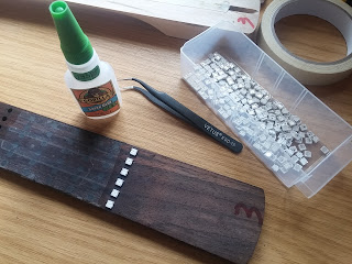
Not wanting to go back on promise meant only one thing - hand-solderingall 96 of the little buggers with a pair of tweezers and some thin-gauge wire. I thought I'd left wire-wrapping behind in the 90s! Luckily there were a couple of laser-cut fingerboards left over from building the last few guitars about a year ago, so I set about super-gluing some LEDs to the underside.


I got the idea from messing about with the electronic board game; having PCBs built for them would be prohibitively expensive, so we swapped the circuit boards for strips of copper tape and hand-building with loose components. By placing the LEDs the right way around, I figured I could connect the data_in and data_out pins together easily, then just join all the power and ground pins to two strips of copper tape on each fret.


It took nearly two days of positioning, soldering, testing, debugging, re-soldering - in between other work - but the end result was quite impressive


Connections between each strip of lights was made up the centre of the fingerboard so the outer sides could be glued to the guitar neck; since the truss rod is down the middle of the neck we wouldn't be gluing the centre of the fingerboard anyway.


A quick rainbow sketch on an Arduino with the FastLED library and we had a rather attractive display. Never mind lighting up frets, learning scales and showing how to play the guitar - I quite fancy another one of these with just the rainbow pattern. I might not be  the best performer at the next Open Mic Night at the Pebbles, but I'll certainly be the brightest!

Thursday, 20 April 2017

Unity, raycasting and line of sight between objects

We're putting together a simple 2D/top-down game that makes extensive use of "line-of-sight" rules as players move around the game world. There are a few ways you can check for line-of-sight but they almost always involve drawing a line between two points, then seeing which objects (if any) intersect this line.

If we were coding this in any other language for any other system, that's probably how we'd do it anyway; create an equation to describe the line between the two points, then "walk along" the length of the line, one pixel/unit at a time, checking to see if the x/y position of any other object in the gameworld is close enough to the line to be considered intersecting with it.

Unity provides this functionality already with its Physics.Raycast function.

Provide the function with a start point vector and a direction vector and it imagines an infinitely long line (the "ray") from the origin, and returns the first object that the ray collides with (if any). There's also Physics.RaycastAll which does the same thing, but returns an array of all objects hit by the ray.

We made use of the RaycastAll function in our line-of-sight checks (although we're building a 2D game, the same principles of 3D development still exist, we just treat everything as if it were all on the same Z-plane). We put three moving objects into our game world, with one of them hidden behind a wall. We then updated the position of each object and ran our line-of-sight checks from the moving object to all other objects in the world. The checks involved raycasting from the movign object to each other object (in turn) and checking the array of collisions.

If the array was empty, there were no detected obstacles along the line, and so we said that there was a line-of-sight between the two (in future development we'll have to include things like facing and field-of-vision and so on, but for now we're just trying to decide if an obstacle exists between two points). If any obstacle was returned in the array, we said that no line-of-sight existed between the two objects.


On the face of it, a simple Raycast function might do the job, as we're only interested - at this stage - in the binary option of "is there an obstacle between these two points". But we wanted to use the RaycastAll function to return ALL objects so that in future we might be able to assign "visibility" to different obstacles. Some obstacles may, for example, be see-through, but we still want them to act as an obstacle for purposes other than viewing. A classic example might be a glass window: you can see through it but it also acts as a physical barrier.

So we don't just want our line-of-sight function to return false if any old obstacle exists between two points - we want to inspect each obstacle type between the points and decide whether or not to include them in our line-of-sight check. So instead of Physics.Raycast, we used Physics.RaycastAll.

Everything seemed to be working just fine for a while; our hidden object remained hidden and the visible object revealed itself in good time. The function correctly identified whether or not there was a line-of-sight between all of the objects. Then something funny happened - despite there being a pefectly clear run between our first two objects, the LOS  function started returning false


Even more peculiarly, sometimes the function returned true (is there a line of sight between these two objects) and sometimes false, depending on which object we used as the source and which was the destination. Yet as we hadn't yet introduced rotation or facing into our function, it didn't make sense that an obstacle was found if we went from A to B but none were found if we went from B to A.

After much puzzling and re-reading the Unity documentation, we eventually worked out the problem. Our ray was continuing beyond the object being tested. So although we thought were asking "are there any obstacles along a ray between these two points?" the function was actually returning "are there any objects along an infinitely long ray, starting at point A and continuing in the direction towards point B?"


Of course, as soon as we moved an object so that there was a wall behind it, the function found the wall. The ray passed through the second object, struck the wall behind and said "yes, I found an obstacle along that ray".

What we needed to do was limit the length of the ray;
The RaycastAll function has an overload which allows you to enter a start point, a direction and a magnitude (maximum length of the ray). We created our ray be subtracting the gameworld co-ordinates of the source object from the co-ordinates of the destination object. This creates a vector describing the path between the two objects. We use this vector as our ray. Having created the ray, we then used the magnitude of the direction vector as the length of the ray.

As soon as we limited the length of the ray to match the length of the vector describing the direction from one object to the other,the function worked as expected, both "forwards" and "backwards" (i.e. it didn't match which object we used as the source and which was the destination).

bool hasLOS(GameObject source, GameObject dest){
   // firstly cast a ray between the two objects and see if there are any
   // obstacles inbetween (some obstacles have "partial visibility" in which
   // case we may or may not want to include as a "hit")

   RaycastHit[] hits;
   bool obj_hit = false;

   Vector3 dir = dest.transform.position - source.transform.position;
   Ray ry = new Ray ();
   ry.origin = source.transform.position;
   ry.direction = dir;

   hits = Physics.RaycastAll (ry, dir.magnitude);
   Debug.DrawRay (source.transform.position, dir, Color.cyan, 4.0f);

   foreach(RaycastHit hit in hits){
      // here we could look at an attached script (if one exists) on the object and
      // decide whether or not this should actually constitute a hit
      Debug.Log("LOS test hit from "+source.transform.position+" to "+dest.transform.position+" = "+hit.transform.parent.gameObject.name);
      obj_hit = true;
   }

   return(!obj_hit);
}


Within the foreach loop we can put some further testing to decide whether or not the obstacle has an effect. So in the case of firing a bullet at a target which is on the other side of a glass wall, we could call the function and ignore the glass object when testing for line of sight (can we see the object behind the glass) but include the object as an obstacle when using the same function to decide if, say, a bullet were to be fired from one object at another.

The same result could be achieved using trigonometry (lots of tan/cos functions) but Unity does provide lots of nice, easy, helper functions, such as Raycast and RaycastAll. Thanks Unity!


Sunday, 16 April 2017

Serial UART hub/network with master/slave devices

We recently had cause to build a simple serial/UART "network" of slave devices. We had a single "controller" device (which receives data from a PC and broadcasts it along the bus) and a number of similar "slave" type devices.

Normally, when it comes to multiple devices along a bus, we'd be thinking of either SPI (broadcast the message to all devices with an identifier in the message to which the appropriate devices repond) or I2C (each device could have its own unique hardware ID to which we address the messages).

But for a recent project we were asked if we could create a serial/UART bus. At first it seemed quite straight forward - simply tie all the TX lines of the "slaves" together and connect to the "RX" of the "master" and invert; tie all the RX lines of the "slaves" to each other and connect them to the "TX" of the master device.

The basic idea is that the master would broadcast a message to all devices, including a device ID in the message. When any device receives an end-of-message marker, it looks at the device ID. If the message is not intended for that device, it simply ignores it.

The theory works great.
Sometimes in hardware it works just fine.
But sometimes it goes horribly wrong.

Now of course if two devices try talking at once, you just get garbled nonsense (so at the end of each message we include a simple XOR sum to check if a message is valid). So this set-up only works if you can be sure that only one device is going to  try to use the bus at any one time.

But sometimes we were getting devices resetting. Not all of them, and not all at the same time. Just some devices, sometimes. Which in turn indicates that one device is trying to drive a line high, while another is trying to drive it low. When this happens, we're effectively creating a dead-short between power and ground; so it's no wonder that the devices are resetting!


By simply putting a diode on each of the TX lines and a pull-up resistor on the "master" RX line we can overcome this problem easily. Now, when a device tries to drive a TX line high, the  current can't get through the diode. But the pull-up resistor lets the TX line (connected to the RX of the master) float high. So the end result is the same.

But if another device drives the TX line low, it's enough to overcome the pull-up resistor, so the entire TX bus goes low (and the master RX line goes low). If one device tries to drive the TX line high and another low, the TX line goes low. The data at the other end might get garbled, but the important thing is that we don't get slave devices resetting.

It's basically the same idea used with SPI communications - drive a line low, release it to let it float high. But if we can't guarantee that our slave devices aren't going to try to drive the TX line high, the diode simply blocks that behaviour. When no devices are pulling the TX line low, it floats high anyway (which is the idle state of a UART transmitter anyway).

Simple.
But a trick worth knowing!

Saturday, 15 April 2017

Creating primitives and textures in Unity

I love Unity. I love that you can write code and compile it to multiple platforms. I love that you can "hit up" the Asset Store and have a game working in a couple of hours. At least, a simple game.

But one of the things I've always fancied doing with Unity was have it load levels (from a web server perhaps) and create rooms and playing areas dynamically. We've played about with doing just that using pre-bought assets (it's not as easy as you think, if you're working on a grid-based system, since most assets have their origin in the dead centre, not on one corner!)

So as a bit of an experiment, we played about with creating a map "plane" from primitives, onto which we'll dynamically load textures. So at the start of the "game" there's nothing on screen - then a few script calls and we'll create some primitive shapes (after all, most floors and walls are not much more than simple rectangles) and apply some textures.

It's worth noting that we're creating a 2D top-down type map, even though we're using 3D shapes (the 3d shapes allow us to work with complex principles such as rotation and line-of-sight later on down the line).


We've set up our camera as orthographic and have it pointing straight down. We also added a directional light and made this a child of the camera - effectively following it as it moves over the map. We also created a "gameWorld" empty gameobject just to hold all our dynamically generated content, in case we need to turn the global world on/off  for some reason in the future.

Now a couple of scripts to actually generate our primitive shapes and to apply textures to them. We're working on a grid-based map and each object we create in our game-world will be placed from the bottom-left corner:


But when you create a gameobject in Unity, the origin of the object is smack-bang in the centre. Which makes getting everything to line up in a grid a bit of a pain (especially if the objects are not perfectly square).


So whenever we create an object that we want to align on our grid, we "wrap it up" inside an empty gameobject and set the local x/y co-ordinates to half the height/width of the object. This way we can place our floors and walls without having to keep applying an offset to get the origin somewhere near the bottom-left corner.


With the gameobject in worldspace, placed at 0,0 half of the floor tile is beyond our 0,0 position (ok, it's only a quarter section, but you get the idea)


By placing the tile inside an empty game object, we can place the parent at 0,0 and offset the child by half the height/width and get our tile to appear where we want it "in world space".

using System.Collections;
using System.Collections.Generic;
using UnityEngine;

public class object_creator : MonoBehaviour {

    Material mat;
    Shader shdr;   

    // if you're using one-square to one-unity-unit keep track of it here
    // (in earlier versions, a 0.5 scaled plane - 5Uunits - represented a board
    // of 8x8 grid, in which case square size would be 5/8 = 0.625)
    private float square_size = 1f;

    // Use this for initialization
    void Start () {
       
    }

    void Awake(){
        shdr = Shader.Find ("Sprites/Default");
        if (shdr) {
            mat = new Material (shdr);
        } else {
            Debug.Log ("wtf");
        }
    }

    // Update is called once per frame
    void Update () {
       
    }

    public GameObject createObject(string objName, GameObject objParent, float x, float y, float z, float size_x, float size_y, float size_height){

        // creates a primitive (cube) wrapped inside an empty game object
        // which is placed at the gameworld position x,y       

        // the position of the (empty) game object is such that the origin is in the
        // bottom-left corner (not the centre as is usual with gameobjects)
        GameObject piece = new GameObject();
        piece.name = objName;
        piece.transform.parent = objParent.transform;
        piece.transform.localPosition = new Vector3 (x, z, y);
        piece.transform.Translate(new Vector3(-square_size/2, 0, -square_size/2));

        GameObject cube = GameObject.CreatePrimitive(PrimitiveType.Cube);
        cube.transform.parent = piece.transform;
        cube.transform.localPosition = new Vector3 (size_x/2, 0, size_y/2);
        cube.transform.localScale = new Vector3 (size_x, size_height, size_y);

        return(piece);
    }

    public void setTexture(GameObject o, string imageName){
        // get the child object in "o" with the name "Cube"
        // (this is the actual shape, the game object is the container)
        GameObject p = o.transform.FindChild("Cube").gameObject;
        // download the texture for this object
        string url="http://your_url/" + imageName + ".png";        
        StartCoroutine (downloadImage(url, p));
    }

    IEnumerator downloadImage(string url, GameObject o){
        if (url.Length > 0) {
            Debug.Log ("loading from " + url);
            WWW www = new WWW (url);
            yield return www;
            Texture2D tex = new Texture2D (www.texture.width, www.texture.height);
            www.LoadImageIntoTexture(tex);
            o.GetComponent<Renderer> ().material = mat;
            o.GetComponent<Renderer> ().material.mainTexture = tex;
            o.GetComponent<Renderer> ().material.shader = shdr;           
            Debug.Log ("Texture set");
        }
    }
}


Our "object creator" script is referenced by our "game controller" script.
When any primitive is created, it needs to be given a material to apply to it; so we create a global material, based on the "sprites/default" shader. This same material can be applied to all our primitive shapes. With a material applied, we can then change the texture property of each shape, with a newly-downloaded image, if necessary.

using System.Collections;
using System.Collections.Generic;
using UnityEngine;

public class game_controller : MonoBehaviour {

   public GameObject world;
   public object_creator oc;
   
   // Use this for initialization
   void Start () {      
      GameObject o;
      o = oc.createObject ("b1", world, 0f, 0f, 0f, 8f, 8f, 0.05f);
      oc.setTexture(o,"board1");

      GameObject o2 = oc.createObject ("b2", world, 8f, 0f, 0f, 8f, 8f, 0.05f);
      oc.setTexture(o2,"board2");      
   }

   
   // Update is called once per frame
   void Update () {
      
   }
}

This script creates two "map tiles" each 8x8 units in size. It places the first at 0,0 and the second at 8,0 (immediately to the right of the first one). The script downloads the image board1.png and applies it to the first tile, and downloads the png image board2.png and applies it to the second tile.

The end result looks something like this:


When we place an object at 0,0 (in world space) it appears in the first square, from the bottom-left corner of the map. If we change the co-ordinates of the object to 3,4 in world space, it appears four squares in and five squares up from our "board origin" in the bottom-left corner of the map (remember our map starts at zero, so at x3, the object should appear on the fourth square in).


A liberal sprinkling of iTween functions and a simple download-map-data-via-xml and we're on the way to creating a top-down game which can load map layout data (and sprites/images) from a website - online map editing here we come!