Monday 29 September 2014

Testing vector collision detection

So we had a little think about using vectors for collision detection. Then we decided rather than dismiss it out of hand, to consider the implications of using vectors instead of bitmap-based collision detection. And it turns out, it could be a Really Good Thing (capital R, capital G, capital T).

We rooted about online and tried to dredge up some basic GCSE-level trigonometry (at least it was GCSE-level when most of us sat our exams about a million years ago - it's probably Masters Degree level or something now!) and came up with some ideas for calculating the rebound angle for things thrown/fired at a wall, even if it has been placed at an angle.

This evening was all about the code.
Here are some screenshots of our testing:


The triangles simply help us to see which way the vector was drawn: in this case, our starting point is to the right and below the point of collision with the wall, which is angled to face the top-right corner of the screen.

Our code seems to have correctly calculated the angle of reflection - and placed the final destination point at the correct distance from the collision.


If we fire our object in a straight (horizontal) line at an angled surface, the angle of reflection (and distance to the final destination point) are once again correctly calculated.


If we use the same angled wall, but draw it as an opposite vector (i.e. from bottom-right to top-left, instead of from top-left to bottom-right) we still get the same result, as expected.


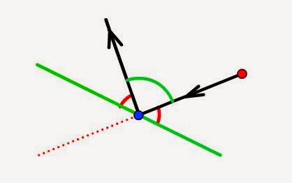
Coming at the wall from the other side gave a peculiar result.
Maybe it's to do with the ambiguity that negative angles create. Or maybe it's something else. Or maybe we've not actually fully understood how to convert polar vectors into cartesian co-ordinates. But something isn't quite right here.

On further inspection, it seems that the vector representing the angle of reflection is simply pointing 180 degrees the wrong way. Before we rip apart our code to find the bug, and spend hours and hours trying to work out if there are two possibilities for a destination if the angle is negative, we threw in a quick and dirty hack: if start.x < collision.x, rotation = rotation+180


This seemed to fix the problem!


 And even worked when the vector was drawn from "underneath" the point of collision - the rebound in this example is still correct: if we draw the perpendicular to the wall, at the point of collision, we'll see that the red line approaches from an angle just less than 90 degrees (and so should bounce off at a steep angle)


If we fire the same shot, but this time change the angle of the wall, the object still bounces off at the correct angle. It looks like our quick-n-dirty hack seems to have done the job!


Lastly, and for completeness, some testing using a vertical approach, just to make sure than a 90 degree or a 180 degree angle doesn't cause the cos/sin/tan functions to bork and throw out some division by zero errors, or something like that!


So there we have it - some successful testing - and in each case, not only do we get the correct angle, but also the distance of the deflected object also looks about right too.

What if we were to introduce a second wall?


Of course, we can see just from looking at the image that the object should hit the first wall, bounce upwards (as shown in the diagram), then hit the second wall, and be deflected back towards the bottom of the screen.

There's no need for us to write a routine which can handle multiple reflections - we can simply use the same one function, and call it recursively, until the path of the object no longer intersects with any vector that makes up an obstacle.

In this case, we could work out where on the first wall we can expect the object to collide. We then create a second, independent path, starting from the collision point, with the final destination point now being our new destination point. We put this vector/series of points into our collision detection routine and see if there is an intersection with any other obstacle vector.
If there is, we simply set the new starting point as the new collision point, and the new destination point as the newly calculated, final (deflected) destination point, and keep repeating until the object no longer collides with any obstacles and simply reaches the natural end of it's path.

It's probably a bit late now to be trying to code up a recursive function (they make your brain ache at the best of times!) but at least we're making some progress.....

Saturday 27 September 2014

Calculating collision detection and rebound angles using vectors

Having given some consideration to how we could use vectors for collision detection as well as calculating rebounds/ricochets, it's time to get coding.

After a number of false starts, and drawing far too many triangles and intersecting vectors, we reckon we've got a workable approach. It's using the dot product of two vectors.
Let's say we've calculated that we have two intersecting lines/vectors - our playing piece is firing a weapon in one direction, but the destination point is intersected by a wall on the map. We want to calculate the angle at which the bullet will bounce off the wall.


Just by looking at the images above, we can see that the angle that the object hits the wall should also be the angle that it bounces off. So when the bullet is fired almost straight at the wall, the angle of deflection for the rebounding bullet is quite steep. However, if the bullet is fired at the wall from a shallow angle to begin with, it almost glances off the wall, with the amount of deflection minimised.

Our task is to work out the angles in the diagrams above. To do this, we're going to create two vectors, but both with a common "origin" - the point of collision. So we create one vector between the starting point and the point of collision, and another vector, from the point of collision to the endpoint of the wall/obstacle being struck


It doesn't really matter which endpoint of the wall we choose. If, after our calculations we have an angle greater than 90 degrees, we can easily find the value of the "correct" angle, by subtracting this value from 180.

Now using online resources for dot products of vectors (it's been a long time since we did any of this kind of trigonometry!) we can calculate the dot product of the vectors to work out the angle between them. This website - http://www.mathsisfun.com/algebra/vectors-dot-product.html - gives a great explanation of how to do this


Once we have an acute angle between the two vectors, we know that the angle of ricochet/rebound is going to be 180 - (2*approach angle). And once we have the angle of rebound, we can add this to the angle of the wall, and use the distance beyond the point of collision to the original destination, to work out where the ricocheted bullet actually ends up.

Now the dot product of two vectors a+b is:

a.b = (ax * bx) + (ay * by)
and this gives us a scalar value (i.e. a "plain" value, not a vector)

There's also another equation to calculate the dot product of two vectors:
a.b = |a| * |b| * cos(angle)
where |a| is the length of the vector a and |b| is the length of the vector b.

Since we're looking to calculate the angle, we can re-arrange this to
cos(angle) = ((ax * bx) + (ay * by)) / |a| * |b|

We're going to need to use pythagoras to calculate the length of the vectors, then add these into the equation, where |a| is the square root of (ax * ax) + (ay * ay) and |b| is the square root of (bx * bx) + y * by). So....

cos(angle) = ((ax * bx) + (ay * by)) / ( sqrt((ax*ax)+(ay*ay)) * sqrt((bx*bx)+(by*by)) )

Phew! That's a mouthful. So with the angle between the vectors calculated, we subtract two lots of these from 180 to get the angle of ricochet.


Now to calculate the final destination point, we can work out the angle between the starting point and add it to the angle of reflection, to get the total angle between the final destination point and the x axis.


And if we can work out the total angle from the x axis to the destination point (the sum of the blue and green angles) we can simply subtract from 180 to get the angle of the destination vector (shown in red in the diagram below):


We already know the length of the vector (it's the bit left over from the collision point to the original destination point) which is marked as "d" in the image above. We also know the angle of the vector (marked in red, above) so we can calculate the value of x in the destination point, with simple trigonometry - x = d * cosA.

Since tanA = opposite/adjacent, and we know the angle, and we know the length of the adjacent side, we can re-arrange this to give us opposite (y) = tanA / x.

After all that, we have x and y values for the final destination point relative to the collision point. So we add these to the x/y values of the collision point, and we (finally) have the absolute co-ordinates of the final destination.

Wow.
That's the theory.
Time to write some code.........

Friday 26 September 2014

More thoughts on using vectors for collision detection

Yet more ramblings, with very little code produced - just ideas that may or may not work in a generic game/physics engine. We've already considered the benefits of using vectors for collision detection. Now it's time to consider how they would actually be useful.

Firstly, using vectors is not without its drawbacks. Collision maps - at the minute simple bitmaps - become much more complex, with each "barrier" in the collision map becoming a straight line vector (we're not even contemplating using arcs and curves just yet - even though it should, theoretically, be possible, we're just sticking to the "simpler" approach for now).

So a building in the middle of a map, at present is represented by a rectangle drawn onto a bitmap. In our new vector-based method, the same obstacle would be represented by four connected points (or four lines, joined at the ends, whichever way you want to think about it!). Instead of testing for collision by "walking along" a path, we now compare our movement/line-of-sight vector (a line drawn from the starting object, to a destination point somewhere on the map can be described by a straight-line vector) with every "vector" that makes up every obstacle on the map.

Wherever two vectors collide, we know we have a collision point.
Bearing in mind that it's quite possible that we may end up with more than one potential collision point (where obstacles are placed one behind another) we'll deal with that later, and work with simple examples for now


Let's say our green line represents a straight-line wall, running from point x1,y1 to point x2,y2.
Our playing piece is at x3,y3, and is looking/firing/throwing an object at point x4,y4.

Using simple trigonometry, we're able to work out the point at which the two lines intersect (using variations on the y=mx+c straight line equation). So far, that re-creates what we already have, using bitmaps. Already we have simple line of sight sorted, but using vectors instead of bitmaps (a binary operation which says is there a line of sight from this point to this point).

What we're particularly interested in is re-using this approach for projectiles, and to work out the angle at which this thrown/fired object, from x3,y3 to x4,y4 rebounds off the wall obstacle, running from x1,y1 to x2,y2. To begin with, we need to calculate the "angle of approach" between the starting point, and the tangent or perpendicular plane of the obstacle.


Since we're using cartesian co-ordinates, we can convert our sets of points into triangles. And using nothing more than tanA = opposite / adjacent, we can work out the angles A and B in the diagram above. But how does that help us calculate the angle of reflection off the green wall?


Since we know that the angles of a triangle all add up to 180 degrees, and we know the angles a and b, it's relatively trivial to work out the missing angle (which we've called C). And since we're after the angle between the "approach" and the perpendicular, we can simply subtract 90 degrees (or pi/2 radians if you're that way inclined).

Incidentally, if ever our angles are such that C is less than 90 degrees, we're effectively approaching the point of collision from right-to-left, instead of left-to-right, so can easily work out the angle on the "flip side" by subtracting from 180 instead.

Now we're getting somewhere. And it's getting exciting. No, it really is. Maths is fun.
Let's say we have our proposed destination point (where the ball would land, bullet would hit etc) if the obstacle was not in the way. To move the object from the start point to the destination point would require some effort or force to get it to move. We don't need to get bogged down with physics equations (though that too would be nothing but fun) we can simply use relative distances  to simplify things:


To get the object to travel from the starting point to the destination point, uses up all it's force or energy or work or effort or whatever you want to call it. So if the object is deflected, say, one third along it's path, it still has two-thirds of it's force/energy (which would otherwise propel it the other two-thirds of the way, when it would come to rest with all it's energy used up).

So we could, at the point of impact, work out the distance remaining to the original destination point, apply the angle of reflection, and work out where the final, actual destination point is going to be.

Now, obviously, at each point that the object is deflected, we need to start our checks for collision again, this time using point C as the starting point, with the final actual destination point as the new proposed destination point. And so on and so on, until the object has travelled the full distance.

What's really exciting about this approach (and it is exciting, and fun, dammit) is that it would allow us to set up complex chain-reaction type obstacles, allowing an object to be thrown/fired and have it ricochet off four or five different obstacles - resulting in an almost random (yet, completely predictable) flight path.

The excitement doesn't stop there.
Hold onto your hats, because this doesn't stop getting better:
Each obstacle could have a "hardness" or "bounciness" rating - reducing the amount of distance remaining on the flight path (or increasing it, if it's a bouncy material) whenever it is struck. So instead of collision detection being something that immediately halts the flight path of a ball/bullet/projectile, it is now something that merely affects it. And we can now have different obstacles with different surface types. Without a single line of code written, this already feels awesome!

We could have soft wall types, which absorb all the energy in whatever has hit them (like throwing a football into a wall of porridge - although a more useful example in a boardgame context might be a laser that hits, and is dissipated by, something like a force field).

We could have bouncy wall types - which actually increase the amount of energy remaining in whatever object has hit them - like throwing a rock at a trampoline.

We could even have "knobbly" wall types, which absorb (reduce the length of the remaining flight path by) say, 20%, but also add a random element to the angle of reflection (having calculated the correct angle the ricochet would ordinarily take, we could add some random value to this, to create the effect of hitting an uneven surface).

In a wild west scenario, we could have both wooden walls (non-reflective, bullets get embedded in them) and stone walls (bullets ricochet off them with a loud ping). For our space game, we could have similar wall types - force fields which absorb lasers fired at them, shiny, reflective mirrored surfaces which make them bounce all over the place.

There's no doubt about it; vectors look fun.
We're going to have a go at coding some up, over the weekend. So, unless they become tricky and just too much hassle to implement in two days, we're very likely to have some of the best collision detection routines in our boardgame apps.

Well, maybe. Surely, it's got to be better than "roll for scatter, roll for distance" as most dice-based games currently use?

MDF for laser cutting

Having visited Weban-Smith in Lewes earlier in the week, the big bouncy nerdmobile was carrying 10 sheet of 8' x 4' mdf (2mm and 3mm thick). Last night was the usual BuildBrighton open evening, so it was time to get busy with a circular saw.

Steve made short work of chopping up the boards into various sizes - A3, A4 and some odd-sized offcuts of about 300mm square. Here's Felix stacking up just some of the sheets we ended up with:


All of the sheets were cut roughly (and in some cases, by eye) so there are probably no more than 6 sheets at a time that are the same dimensions! But that's quite a stack of mdf we have now, ready for laser cutting.

We worked out that a single 8'x4' sheet should yield about 44 A4-sized sheets.
With ten large sheets of mdf, we could have ended up with over 400 pieces! At £70 for ten sheets (including VAT) that would be around 16p per A4 sheet - super cheap prototyping material! We left some sheets double-sized (A3) and had some peculiar 12" square bits, but must still have had about 300 smaller sheets, when all was done.

Steve and Jason can handle massive oversized A3 sheets (up to 500mm) in their laser cutters, whereas our LS3020 can just about cope with slightly-bigger-than-A4. So now with everyone with a healthy stack of 2mm and 3mm mdf, there's no reason not to be making cool (laser-cut) stuff all the time!

Thought experiments for collision detection using vectors

We've been using our almost-pixel-perfect line-of-sight algorithms for a while now, and they work really well. We've made about three or four revisions to the actual games using them, but the underlying method of detecting collisions between a moving and a stationary object remain pretty much the same each time.

The general idea is pretty simple - take a bitmap snapshot of the playing area, from the two points you want to test a line-of-sight between, then walk along the diagonal to see if there are any non-white pixels in the way. Wherever a non-white pixel is encountered, there's an obstacle and a collision is detected.

For shooty games, this is great - we can use the same routines not just for line of sight, but to resolve when a shot is fired at a target. We even know exactly where the place the little "bullet explosion" - should the bullet collide with anything along it's intended path - and then a quick loop around the objects on the screen, comparing their distance from the point of contact allows us to include varying degrees of damage from anyone standing within the "blast radius". This method not only allows us to have simple bullets flying around in our games, but also explosive projectiles, like rockets and grenades, which can have a large impact in the centre of the explosion, with lesser effect radiating outwards from the point of explosion.

Exactly the same technique can be used for sports-sim games, for throwing a ball from on spot to another - if another player character is in the way (i.e. would get struck by the ball) they can attempt an interception.

Something that did come up in conversation - and it's an idea that we really should just put to bed as "for another time" but it just won't go away - is reflected shots and ricochet. What if the bullet/ball were to hit an obstacle, but continue moving? Our current routines simply stop the movement dead - this is fine for bullets and projectiles which might otherwise embed themselves into any obstacle hit, but a bit unrealistic for things like sports games and throwing things around.

The problem with our current collision detection is that is uses a point and not a vector to determine collision. This means that we have no idea in which direction the ricochet should travel:


The first problem with our current approach is that the angle of reflection/ricochet is dependent not just on the angle of approach, but also the angle of the object striking it. If the blue dots in the example above represented points along a wall, for example, the angle/facing of the wall would have an impact on the angle of reflection.


In order to correctly show the angle of ricochet, we need to be able to calculate the angle of approach to the perpendicular plane of the object/shape being struck. We can then make the object bounce off, at the same angle:


All this basically leads to us defining our obstacles layer not as a bitmap that we can walk along, looking for non-white (or non-transparent) pixels, but describing each obstacle as one or more vectors.

We'll need to convert our starting point and destination point (e.g. character moving could be the starting point and the target being shot at - or place where the ball is being thrown in a sports simulator - could be a destination point) into a vector. As a vector, we can write this as an equation for a straight line, y=mx+c.

In this equation, m is the gradient of the line and c is a constant value describing where the line cuts the y-axis when x has the value zero. This is a typical equation for a straight line.

If we were able to describe - in this case, for example, a wall as a vector - i.e. a straight line passing from one point to another - we could also express this as a straight line equation y=mx+c

Using simple trigonometry we should be able to calculate the gradient of each straight line, and thus, the collision point (where the two intersect) if there is one, is the point where the two equations are equal. Solving equations is probably best left for another blog post - the idea is to demonstrate that this is not only a feasible alternative to our previous method of collision detection, but an enhancement to it.

Once we have found our intersection point (if one exists) we can simple report back that intersection point (as we currently do, but using bitmap probing) or we can calculate the angle between our "approach" to the obstacle, and its perpendicular: this gives us the angle that we should bounce any object (ball, bullet, projectile) off it.

That's it for now.
No code written. Nothing actually put down on paper and tested - just a theory. But it could prove to be quite a useful one. For objects on the map (such as playing pieces) we could create a bounding box (four vectors arranged in a square) and use these in any vector-based collision detection (it's not likely that we'd want to "bounce" anything off a playing piece, but for completeness, it would be nice to be able to use the same routines to see if a playing piece is acting as an obstacle, as for walls and immovable objects too).

It's possible that this approach might lead us up a dead-end and we end up wishing we'd never even tried it. That's fine. If that's what happens, we've always got our bitmap based method to fall back on. But there's also a chance that it could add some really exciting physics to our gaming engine. And for that reason, it's got to be worth at least giving it a try........


Wednesday 24 September 2014

ExpressPCB to Gerber software

As ever, we're always planning one step ahead with our projects. So while we've only just got everything ready to hand-print a few prototype boards, we're already considering the possibilities of having boards manufactured (there are UK-based companies that can manufacture medium quantities of PCBs at roughly the same cost as buying in China - without the 8 week delay and import duty costs!).

Manufacturing PCBs means Gerber files.
And Gerber files mean having to move away from our preferred PCB editor, ExpressPCB. We've played with RS Component's own offering DesignSpark and found it to be a pain to set up and use. Freeware KiCAD gets good write ups, be when you're using software that doesn't even snap to it's own component pads, something isn't quite right!

We've used DipTrace in the past, and that was ok.
In fact, it was quite good. But most of what was learned has been forgotten, and the idea of spending a chunk of money on a licence for, and relearn all the quirks and get used to the interface for, some software that we're only likely to use only every now and again is a bit depressing.

For quick-n-dirty home-etching, ExpressPCB still rules!
We use CutePDF to print our ExpressPCB designs out and etch from there. But not many fabrication houses will manufacture PCBs from a PDF file! If only there was some way of coverting the easy-to-use super-quick-to-create ExpressPCB files to gerbers....


http://www.robotroom.com/CopperConnection/Converting-Express-PCB-Files.html


David Cook's Copper Connection is not only a PCB editor in it's own right - with an interface and workflow very similar to ExpressPCB - it's also an importer of ExpressPCB files. In fact, using the Open File dialogue even displays a handy thumbnail of all the ExpressPCB .pcb files on your computer!


And the best bit?
Of course - it can not only open ExpressPCB files, but it can export them as gerber files, ready to send to your favourite PCB manufacturing lab. For us, it's the perfect piece of software!

Now let's get this straight.
It's not free. The "studio edition" costs $49.
But many of the gerber-exporting alternatives we were looking at were not free either. DipTrace isn't free. To do anything beyond 100mm square boards in Eagle isn't free. Commercial licences for most pcb editing software are not free.

Not only is Copper Connection substantially less than a lot of other PCB editing software, it also means we can continue to use our favoured, easy-and-simple ExpressPCB software for designing and laying out boards, without having to learn a whole new, complicated PCB layout package.

It's win-win.
So that's a whole evening wasted, installing, trying and rejecting lots of different PCB editing software. We can now just stick with what we know, and use Copper Connection much as we do Inkscape for converting vector images - to load in one file format and get it to export as another, more useful one.

At least we can forget about PCB manufacture for a little while, safe in the knowledge that we don't have to recreate our fully-tested-and-working PCBs in some other software application and hope we didn't screw anything up while re-drawing the boards: we can now simply export the very boards we've home-etched and send them off for manufacture!


Sunday 21 September 2014

Progress without actually doing much

Tonight we managed to get a new vacuum head laser cut. It was only a small job, but seemed to take ages to get just right.

Since the last one had problems with a single elastic band being too tight, and two bands being too slack, the new design incorporates an adjustable height mechanism. This way, we can add just enough tension in the bands to act like springs, to get the vacuum pen to return, without overwhelming the puny little 9g servo we're using.


Straight off the laser cutter, and straight onto our cnc pick-n-place machine. Now, by slackening off the top nuts, we can adjust the height of the top piece by rotating the nuts (screwing them either up or down the M3 bolt connected to the bottom piece) immediately beneath it. This worked surprisingly well.


We also adjusted the size of the holes in these pieces - dropping them from 10mm to 9.4mm. We measured the barrel of the pen with some digital calipers and it reported that the width was around 9.4mm (they were only cheap calipers, and tended to vary between 9.35mm and 9.48mm along the length of the pen!)

With the new, tigher-fit holes, the pieces lock around the pen barrel using just the friction between the mdf and the pen (is this what is often called an interference fit?). Anyway, the result is quite pleasing - as the servo arm lifts, the entire pen lifts also. When the servo arm goes down, the pen snaps back into exactly the same place, every time.

This did get us thinking about how it would actually work in operation.
So far, we've not given much thought about rotating pieces when placing them on the PCB. In fact, since this machine was only every designed to be semi-automated (it will pick up a piece and place it over the correct place on the board, then wait for an operator to confirm the position is correct - jogging the head up/down/left/right if necessary - then hitting a button to actually drop the piece down) we thought that simply rotating the pen by hand would suffice to begin with.

But now things have got a bit tricky.
When the pen was a very loose fit in our pen-raising mechanism, this would work fine. But with a tight, snug fit, it's not really possible to rotate the pen at all now - as it would require the attached elastic-band-and-servo assembly to be rotated also.

The obvious answer is, of course, to ensure that the component to be placed is facing the correct way around before the pen picks it up. Which in turn means that our automated parts feeder - which worked so well in earlier trials - is effectively redundant. So we're actually making progress by removing parts of the machine. This is the kind of progress we like - improve things by simplifying them!

It's not unreasonable (although it feels like a bit of a cop-out) to have the vacuum head simply move to a "ready" location, and present it with a component (already turned around to the correct orientation) before switching on the vacuum pump, to draw the piece onto the travelling head.

How the component is prepared can be developed as a separate, independent part of the project. To begin with, we could even just place the component on a piece of board and move it - by hand - into position, under the head, before starting the pump-on-head-up-move-to-position-wait-head-down routine. In future, we could develop a "component preparation" module for the pick-n-place machine, which would automatically wind the next component from the reel, and rotate the component (rather than rotating the head) ready to be picked up.

But for now, we can actually make further progress with our machine by taking that bit out and worrying about it later.

In fact, were it not so late, we'd probably be ready to give the machine it's first test run: we've got x/y axis moving nicely now, the entire pen moves up and down with the servo, the vacuum pump can be triggered manually when required, and the components can be presented to the head, rather than have them pulled out of an automatically fed tape.

The firmware needs a bit of revision (it's currently using a function-blocking serial-poll method of getting data, which is just plain shonky) but that's all that's really stopping us from giving it a spin. So maybe tomorrow night we'll get the firmware updated and perhaps after that look at building a nice application to run it from a desktop computer.

Hardware based, interrupt-driven serial/uart data parsing here we come.............

Friday 19 September 2014

Vacuum head fail

It's been a little while since we managed to do any work on our CNC pick-n-place system. With real life and work and the Scottish Referendum getting in the way (ok, maybe not the referendum) there's not been much activity on this little project for over a week.

And - given we've got some screens prepared for printing multiple copies of our board game PCB - it's time this was finished so we can start using it to populate circuit boards with SMT components!

So far we've got our x/y axis moving and an SMT parts feeder running. Now we just need to connect up our vacuum pen and lift it up and down, and we're ready to try the whole thing out!

For our z-axis (pen up/pen down) we're planning on using a servo. This worked well for us on our CNC drilling machine of a few years back, but it's going to need a little modification. For the drill, we wanted to force the head of the drill beyond the surface of the piece being cut (so that the drill would in fact drill a hole in the piece). For our pick-n-place, we want to put our SMT component on the top of the board, but not try to ram it all the way through!

Because we don't know at this stage exactly how thick each of our components is likely to be (IC chips are likely to be thicker than 1206 resistors for example) we can't be sure, beforehand, how far down we want to drive our servo, to place the piece on the board. What we were looking for is a spring-loaded system, so that we can raise the pen/head up, but when released, it returns (downwards) under spring tension. When the component is on the surface of the PCB, the spring can't ram the piece any further down into the board.

This simple modification should mean that we can easily accommodate SMT components of varying thickness.

Of course, being cheap, and looking for an easy win, we replaced springs with elastic bands, mounted the servo onto a pen-holder, and dropped the vacuum pen into place:


When the servo is activated, it lifts the pen upwards, against the tension in the elastic bands. When the servo goes the other way, it does not drive the pen downwards - it simply moves out of the way, and allows the elastic bands (springs) to pull the pen back to the surface. If the tip of the pen plus the component it is holding is resting on the PCB surface, the elastic bands can't actively drive the pen tip any further downwards (potentially damaging the tip of the pen).


Despite it being a historic night for British Democracy (the Scottish/UK referendum was taking place) a few of us turned up at BuildBrighton last night and tried the vacuum head assembly on the actual CNC frame.


The results were less than impressive.
It turns out that the tension in the elastic is too great for the servo to overcome. So when trying to drive the head upwards, you can hear the little 9g servo straining - but there is no movement.
Remove the elastic bands, and it can flip the pen holder attachment up easily (though without the bands to offer some resistance, the pen sometimes jumps out of the holder!)

We tried using two rubber bands (making them longer, and thus putting less strain on the servo). This worked, but two bands tied together were simply too "floppy". So we've decided to try making an adjustable height mechanism on the pen holder. By adjusting the height of piece that the elastic bands connect to, we should be able to adjust the amount of tension in the bands (and thus, make it easier/more difficult for the servo to lift the head).

We also need to change the way we drive the servo, in our firmware.
At present, the servo does not "lock" into place. We issue our 20ms pulses to get the servo to move into position, only long enough for the servo to move into place. During this time, the firmware does nothing else. This means that once the servo is in position, it is not longer being actively driven into place (and can be moved, by hand - or by the tension in the elastic bands - into a new position). We don't want to use a timer on the PIC to re-issue the servo position every 20ms, as this might interfere with our (non-buffered) serial read instructions, and result in garbled data.

So we're going to create a dedicated driver board, just for our servo. It will be a cheap PIC based board, with it's own dedicated timer, driving the servo to a new position every 20mS. This will cause the servo to lock into place, and will also mean we don't have to worry about running everything off one chip, and worry about interrupt routines colliding and potential data loss.

Last night felt light a we'd failed in a lot of respects. But, given that we came away with a whole load of ideas on how to get the head working, it was actually quite a productive night. That doesn't quite seem right - getting something done on a Thursday evening... Maybe we can convince the Scottish Parliament to hold a referendum every Thursday, and see if it makes our other Thursday nights a bit more productive too!


Sunday 7 September 2014

More pick-n-place feeder testing

Our earlier trial for a feeder worked ok. But was a bit wonky at times. The tape could easily jump off the sprocket, and as the motor span, the tape wouldn't necessarily advance properly.

So this afternoon, it was down to the Nerd Unit to carve out some new designs!
We stuck with the same principles - it seemed to work, after all - and just made a few slight changes to improve performance.

Firstly, we reduced the number of teeth down to 20. This reduced the overall size of the cog, which we weren't thrilled about - but it did mean that the mounting bolts for the motor were no longer in danger of catching on the teeth/tape as it passed through.


The height of the channel that the tape travelled through was reduced from 3mm to 1.3mm, so that the tape would  be pushed closer to the teeth of the cog as it rotated (and it had nowhere to move to, veritcally, so reducing the chance of it skipping off the teeth).
We also removed part of the top of the feeder, so that we could push the sides of the device closer together, but still gain access to the surface-mount component (in this case a 1206 resistor).


A small shim was placed in the top channel of the feeder, to reduce the amount of room the tape had to move left-to-right.


Now the tape couldn't move left-to-right, nor up-and-down as the sprocket rotated, it was time to try the new design out....


The result was a much smoother, more accurate tape advance feeder. The teeth engaged with the tape every time, and the tape advanced with no slipping or missed feeds. Except....

We forgot that with our smaller sprocket, with fewer teeth, we needed fewer steps to make the tape advance by the 4mm between each component. A quick bit of maths told us:

The stepper requires 4096 steps for a full revolution (according to the datasheet) but we're using single-stepping, not half-stepping, so this is 2048.

2048 / 20 = 102.4 steps per 4mm distance.
After a few tries, we got it almost right. But every now and again, the tape would advance too far. Even allowing for the rounding error (we would make the motor move 102 steps twice, then 103 steps every third time) the tape wasn't advancing quite correctly.

We soon discovered that our stepper motor wasn't quite performing according to the datasheet. Maybe it's because we're driving it directly from a 12v supply (the same as the steppers on the x-y chassis) but 2048 steps seemed to take the motor just beyond one complete revolution.

We coloured one of the cog teeth (so we could see where it started, and where it ended up) and made the motor spin 2048 steps. After a number of trials, the coloured tooth definitely appeared to be further round that from where it originally started.

With a bit of Steve-coding (trying different numbers until something appears to work properly) we discovered that 2036 was the more likely value to get a true single revolution. Now 2036/20 is 101.8 - which means that some times we should be using the value 102 and sometimes 101. For a small number of components (up to, say, 100) the difference is probably negligible. But over time, that cumulative error could make the alignment of the components and the picking head go all to cock.


We'll hack in some nasty Stevecode to get around it for now. And maybe a more permanent solution might be some simple jog buttons on the feeder - so after we've filled one board with it's resistors, we can jog the feeder forwards/backwards to get it exactly in position before starting the next run?

Given the quality of the components we're using, we're not going to worry about getting it exactly right - our stepper motor is supposed to have 2048 steps per revolution, but it's more like 2036. There's also quite a bit of backlash in the gears (it shouldn't be an issue if you're only ever driving forwards, but gives an indication about the build quality of the motor). We're also using an mdf container, which may, or may not, create additional friction between the tape and the sides of the feeder, which the cheap, low-quality motor has to overcome.

Rather than fix the problem properly, with decent quality components and an aluminium milled body for the feeder, we'll just acknowledge the potential problem, and provide a means of correcting any cumulative errors quickly and easily (a method which may still be necessary, even with expensive, top of the range parts too!)

More pick-n-place testing: feed roller

There was a bit of debate about how to do the tape feeding mechanism - and whether we should even have one at all. At first we were going to have a manual tape advance (i.e. you placed the tape on the base of the machine and after each component had been taken out, simply pulled it by hand to get it into position, ready for the next time). But this was deemed a bit lame.

So then we thought about having pinch rollers - simply feed one end of the tape into a mangle-like pair of rollers, and drive the bottom roller a set number of revolutions, in order to move the tape forward. This seemed like a great idea, except if the tape is not fed exactly straight into the rollers, by the time five or six components have been dispensed, the tape could have wandered laterally across the rollers.

So, the more complex, tractor-feed device was designed and cut from mdf.


We found a website which demonstrated the "standard" measurements for SMT tape reels. Apparently, there was a standard, but it got complicated adhering to it, with all the different tape and component sizes, so it was abandoned. But most SMT component manufacturers still use the most commonly used pitch widths and hole spacings, so we stuck with those.


We created a simple gear, with 24 teeth (it seemed sensible to go with a multiple of 8 for some reason and 16 created a very small gear) and set the tooth pitch at 4mm. Because the gear has to fit inside holes not more than 1.5mm across, we had to adjust the image in Inkscape a little bit, and cut the final gear, not from 3mm mdf, but from 0.8mm birch.


A crude test, but it looks promising - the strip of 1206 resistors fit perfectly around our feed wheel.
The idea is to have the tape enter and exit from the same side of the feeder, so we built a simple track around which the tape would bend.


The other side of the feeder is then clamped in place, holding the tape between the "runners" built into the frame. At present we have only washers and bolts to set the spacing between the two sides, but it seems to work well enough.


One of our trust 28BYJ-48 super-cheap motors will provide the driving force. These motors, from memory, have a large number of steps per revolution (internal gearing means it's something crazy like 2048 or 4096 steps per revolution!). Since we're always driving in the same direction, we don't have to worry so much about backlash, like we did when we used these motors on our super-cheap cnc-drill.

Here's our SMT parts feeder during the very first trial run


The spacing isn't quite right for the tape - our slot is much wider than the tape, allowing it to "wander" and not quite line up with the teeth on the gear. But for a first test, it's very encouraging.

Here's the feeder advancing by approx. 4mm per command.
Since our tape has a single resistor placed between every hole, we know that they are exactly 4mm apart. Other components and other tape manufacturers may vary, so we need to allow the number of steps to advance to the next part to be variable, as well as to cater for different tape widths.


Thanks to the 28BYJ motor, advancing to the next part in the reel is actually very quiet. Not something we were even considering, but it's a pleasant surprise!


MDF framed pick-n-place moving

Last week, we hacked together an mdf-based pick-n-place frame. Actually, it's just a bog standard x/y cnc axis, but it's going to form the basis of our pick-n-place machine, so that's what we're calling it. We hooked up our stepper motors to some L298N based (dual H-bridge) driver boards and using a bit of investigation, worked out the required coil-activation sequence (by putting power onto each of the IN1, IN2, IN3 and IN4 pins on the board, in sequence, until the motor rotated smoothly without jumping).


Once we had our coil-activation sequence (in our case, it was IN2, IN3, IN1, IN4, to get smooth, single-step rotation) we simply cobbled together some firmware which would accept serial data, and activate the stepper motors.

Our principle of moving is simple:
The PIC microcontroller (we went with a massive 16F877A because a) we had loads hanging around and b) they have loads of i/o pins, which gives us scope for expanding and using limit switches, parts feeder and so on, without having to expand the mcu) accepts serial data in the format -

zero byte (start of message marker)
command byte (value of 0x01 tells it what follows is position data)
parameter data (changes depending on the command byte sent).

When we send a command byte of 0x01 (positional data) the mcu simply compares the incoming data (the destination co-ordinates) with the currently stored x/y/z data. If the destination value is different to the current value, for each of the axes, the mcu drives the stepper motor one step closer to the destination value (updating the x/y/z position values along the way).

While any of the x/y/z destination values are different to the actual x/y/z positions, the mcu displays a "busy" indicator (for our example, we use a red LED). When the controller sees all axes are in their appropriate destination positions, it lights a "ready" indicator (a green LED) and sends a single byte (0xFF) back to the controller - like a "clear to send" indicator.

The video below shows the CNC being tested with the serial-based firmware


During the video you can see the command sequence
00 01 02 00 02 00 00 00 being entered

This tells the mcu:
00 - start of message
01 - position command
02 00 - set the x axis to 512 (the two byte value represents a 16-bit integer)
02 00 - set the y axis to 512
00 00 - do not move the z axis (we don't actually have one attached yet)

When the data is sent you can see both axes move at the same time.
As they are both increasing one step at a time, they both move together.
It is possible to update just the position of one axis - in this example, we changed the value of the y-axis and the x-axis remained in it's unchanged position (we also got the wrong steppers connected to the x/y pins: we tend to think of the bed as the y-axis and the gantry as x, since we normally position the cnc with the gantry going "across" our viewpoint, but seeing them the other way around is equally valid, depending on where you consider your x-axis).

At the end of the video, you can see the y-axis crash into the end of the gantry, and hear the belt slipping. This was a mistake in the data entered - we set the y-axis to 0x2000 instead of 0x0200 (in decimal, that's the difference between telling it to move 8,192 steps, and 512 steps!). The video ends just as we pulled the 12V supply from the motor controllers, to avoid damaging or stretching the belt.

We're only using single stepping (activating the coils in a simple 2,3,1,4 sequence) rather than microstepping. Whether or not this gives us the accuracy for placing components we need remains to be seen - 512 steps seems to move the carriage quite a distance (though we could go from 4 single steps into 8 micro-steps, using the "inbetween positions, by activating two coils together, to give better accuracy if it's needed).

From testing though, it looks like the next job is to add some limit switches on the end stops!


Monday 1 September 2014

28mm terrain buildings in FreeCAD

Having spent a few hours getting familiar with FreeCAD, we decided to create something actually useful: some exploded diagrams of how to construct our 28mm wild west buildings. Having taken out the mistakes we found during assembly, we just need to finalise the designs - add in a few more tabs, to make construction just that little bit more intuitive - and we can create 3D models of all our buildings.

Starting with the simplest (and before we added in extra locating tabs, d'oh) we managed to put together a reasonable 3D model of our "bank" building


A few components got accidentally deleted, as we battled with ungrouping "compound parts" (simply delete the overarching compound and the component parts become individual again) but the end result was quite impressive, for our first real venture into creating 3D models (rather than just re-positioning models created by someone else).

So now we just need to decide where to add in the extra locating tabs, and we're ready to produce some step-by-step assembly guides - complete with 3D exploded diagrams!

FreeCAD for assembling 3d laser cut shapes designed in 2d in Inkscape

During the construction of our cnc frame (for a pick-n-place machine) we had a number of revelations. The first being that we're actually not that great at realising 2D drawn designs in 3D!
All too often, we'd line parts up and realise they were out by about 3mm - usually the thickness of a piece of mdf, where we'd forgotten to allow for abutting edges or to compensate where one piece meets another.

Rather than go to the trouble of cutting and assembling (and later, trying to fudge, fix, and eventually throw away) pieces, only for them to end up in the bin, it'd be far easier - in the long run - to assemble everything virtually, on the screen.

Steve does this a lot, using 3DS Max. We looked at that a few years ago, but it has far too many buttons for us! What we needed was something simple to use. Google Sketchup is great for layout out shapes into a 3d design - we'd already done this quite a bit with our spaceship terrain a few months back - but it doesn't have the ability to import and extrude your own CAD drawings; everything has to be created from scratch in Ketchup, which is a bit of a chore.

You can import your own drawings in Sketchup, but it requires a Pro licence - costing about £500. So we need something simple, and cheap, to create our 3D master pieces.

OpenSCAD is a popular 3D package used by a lot of nerds and geeks and is great for creating shapes using a programmatic approach, for boolean operations, additions and subtractions and the like. It can import flat svg files and extrude them, to create 3D models from 2D cad files. The only issue with this is programmatically placing each shape gets complicated, very quickly!


So we need something easy, cheap, able to import svg (or other vector formats) and with a simple interface for moving the pieces around.

Luckily FreeCAD ticks all the boxes! Of course, like starting out with all new applications, the interface takes a bit of getting used to, but it's actually really easy to turn a 2D CAD drawing into a 3D representation of the project. To start off, simply import the SVG of the CAD drawing


Now, make sure the drop down menu is set to "Parts" (for parts editing). Without doing this, half of the toolbars either disappear, or are greyed out. With all of the CAD drawing selected, hit the "extrude" button (a box with an up-arrow against it) and enter the height 3mm. The CAD drawing will magically become a 3D image!

Even if the CAD drawing has "removed parts" from planes (e.g. a drill hole cut into a rectangle) these don't come through in FreeCAD. The shapes exist, but they need to be removed, using a boolean operator. Luckily this is easy enough. Select the part you want to keep, then - holding down the control key (not shift, as is common in most applications for selecting two or more parts) - select the part to be removed


Hit the boolean subtract button, and the selected piece is cut out of the main shape. It's a simple enough job, just a little time-consuming if you've got loads of tabs and slots to cut out.

With all the slots and tabs cut out, we're ready to start assembling. Having only Sketchup as a comparison, in which we had to install an edge-align tool as it doesn't have one as standard, we've no idea if how FreeCAD works is typical, but it's certainly intuitive enough to get going really quickly.

Start off by selecting a piece - the first piece selected will remain in place. Then, with the control key held, select a second piece. The second piece will be moved to join the first, stationary piece. With both pieces selected, use the Edit -> Alignment menu option


There is no toolbar for this, nor is it available in a pop-up menu, so you must use the Edit menu. This opens the alignment screen(s).


Now it's a case of stretching your head around which parts will be touching, once the second piece has been moving into its final position (strangely, the second/moveable piece appears on the left of split screen).
In this case, we want our end piece to stand up at 90 degrees to the base. Rather than mess about rotating pieces, you simply select enough points to allow the application to work out the required rotation.

In the example above, we've selected two points, which will line up the tabs on the vertical piece, with the slots in the base. But we need to provide at least one more point, to align the bottom edge of the vertical piece with the bottom edge of the base.

You can align faces, edges or vertices (corners). By selecting a vertex, you're often actually aligning two edges at once, so we tend to stick with vertices where possible - though sometimes it's handy to be able to say "this edge should run along this edge" or "this face should be touching this face" to help get the rotation correct.

After successfully aligning a few pieces, our 3D design is starting to take shape


And finally, we get to the whole point of learning how to use a completely new CAD package, and the reason behind spending hours longer in the design process - it's cock-ups like the one below we're looking to eliminate by assembling everything on screen before sending our designs to the laser cutter


We've done the classic trick of offsetting our tabs by 3mm (the thickness of the mdf) and forgetting to adjust it in other parts of the drawing. This actual mistake cost us two sheets of mdf. Not much in terms of materials costs (it would have been a lot more if we were using acrylic!) but a lot in terms of time and effort (especially since we wasted about half an hour trying to bodge/fix it, instead of just cutting a fresh piece!).

3D CAD is a great way not only to visualise the final project, but also a really useful way of ensuring everything lines up properly before even going anywhere near a laser cutter (or cnc router, if that's what you're using). This is especially useful if you're going to be using slightly more expensive construction materials.

But one of the great things that 3D CAD allows us to produce is a set of assembly instructions. So in the true spirit of sharing designs and ideas, we can now easily share instructions on how to assemble the pieces, with anyone daft enough to download our plans and use them in the first place!


CNC pick and place laser cut frame

A few Thursdays back, we started a second version of our CNC frame, for a semi-automated pick-n-place machine. We'd already started one frame, but decided, in the end, that it didn't really follow the idea of small-scale, desktop manufacturing. It was a beast of a thing - really heavy, cumbersome to carry around, took up loads of room, and had massive stepper motors flying up and down the gantry.

A second version followed, a few weeks back, made from some metal brackets from B&Q and a few sheets of Dibond. It was easy enough to put together, but the overall finish wasn't very impressive. It doesn't matter how smooth your linear rails are, and how much you grease the rods - if the rails aren't perfectly parallel, you're going to get binding somewhere!

Steve pretty much said as much last week - as we were discussing the poor performance of CNC frame V2.0 he suggested that the only way to get a decent CNC frame, ensuring everything was square and parallel, was to CNC cut one. Our desktop CNC is still waiting to be set up, so that was out. But we do have a fully functional laser cutter. That's just a CNC with a laser instead of router isn't it?

It took about 6 hours, to design, cut, fit, re-design, re-cut, refit, scrap-and-start-again and finally produce our laser-cut mdf CNC frame. The first lot of shapes came out quite quckly.


The y-axis was up and running in next to no time.
This is actually the fourth version, strictly speaking - there was an earlier mdf version that we aborted after about two hours, because making space for the steppers and everything else was just getting really difficult.

So in this version, the end piece (where the y-axis rails fit in) extends 33.5mm beyond the base plate. This allows us to put a small nema14 stepper motor under the actual frame (you can just see the pulley attached to it, on the left hand side of the bed).


The uprights are reinforced by gluing two-similar shaped pieces side-by-side. The inner piece has slots for the x-axis cross-member, while on one of the uprights, we made a little box to house another nema14 stepper motor.


The x-axis gantry, ready for fixing over the y-axis travelling bed. At this stage, the gantry is independent of the other part of the CNC. We've yet to decide how to fix the two pieces together. We're even toying with the idea of being able to dismantle the overhead x-axis (by unbolting the "feet" of the gantry from a baseplate) to make storage a little easier.


For the x-axis, a single linear bearing will sit on the one rail with skate bearings fixed on the top and bottom. The skate bearings will run along the back piece, to stop the main bearing from rotating as it travels left-to-right across the gantry.


The final design is just over the size of an A4 sheet of mdf. This means the device will be small enough to be portable, as well as comfortable to use on a desktop, without taking over half of the room, when in operation!


Next time we'll be fitting the x-axis rail and fixing belts to the motors to actually get something moving!