Sunday 30 November 2014

Dynamic lip sync using AS3 and Flash with mp3 and Audacity

Sometimes it's nice to try flexing your coding muscles on something small and achievable in a single sitting, rather than having to load an entire, complex, multi-module application into your head, just to edit a few lines of code.

This weekend, we spent some time thinking about the kinds of games we'd like to create for our electronic board game system. Not just vague genres, but how to actually implement some of these ideas into a game.

For example, we're already decided on a fantasy football game. That's a given.
But wouldn't it be great to have some online commentary as you play? As a playing piece is moved down the pitch, and tackles attempted, the ball fumbled and so on, some disembodied radio-commentary-style voice could read out the action as it unfolds.

We're pretty much decided that such a thing would be really cool. But then - as often happens with good ideas - someone went at took it a stage further. Why not have an animated commentator, in the top of the screen somewhere? A John-Moston looky-likey maybe- delivering his audio commentary into a microphone, on the screen?

That would be cool. But could prove quite tricky to implement.
After all, it was a long time ago that a few of us put together a perfectly lip-synched "Nothing Compares 2U" animation with a couple of 3d characters (using Hash Animation Master if you're interested!). That was only three minutes long and the animation took about three weeks, of scrubbing, listening, manually setting key frames and so on. That would be a massive task!

Michael (who had a hand in organising the phoneme shapes for our original animation) suggested an alternative, slightly-cheating-but-good-enough-for-a-bit-of-fun approach to lip-synching, using on-the-fly processing: moving the mouth to match the amplitude of the sound coming out of it.

This seemed a bit of a cop-out, but it does ensure that the most important parts are at least in sync (i.e. the mouth is closed at the start, and after completing a sentence). The bit inbetween, where words are spewing out of the mouth will just be more like a "flappy-gob" style of animation. But it's better than hand-crafting the keyframes for every phrase.

Michael also suggested that if the lip sync is being done on-the-fly, then there's no reason why we couldn't make the audio interchangeable: simply load an mp3 file at runtime and play that, to make the mouth animate on-screen. Load a different mp3 file, get a different set of sounds, but re-use the same lip-sync routines to allow for custom, user-generated content.

This is already getting way more complicated that anything we wanted to put together. But there's also something about being given a seemingly impossible challenge and a tight deadline to complete it by!

So we set about planning how things might work, in our fantasy football game.
To begin with, we'd have one, long, single mp3 file, containing loads of stock footballing phrases and cliches. These would be "chopped up" at runtime, and different sections of the mp3 played at different points during the game.

While the mp3 is playing (the commentary is being "said" by our onscreen avatar) the actual sound byte data would be analysed, an average amplitude of the section calculated, and an appropriate mouth shape displayed on the screen.

So far so easy....

For the sake of testing, we mashed a few Homer Simpson phrases together into a single, larger, mp3 file in Audacity.  This great, free, audio editor allows you to create a "label layer" and place labels at various points during the audio file.


It's worth noting that as you select a position in the label track, the "playhead" in the audio track is updated to the same point in the audio data: this helps line up the labels with the actual audio to be played.

We placed some simple titles at specific points in our audio file, to indicate which phrase was being said at which point in the file.


With all our labels in place, we exported the label track as a text file.


It is possible to stretch each label, to define a start and an end point. We didn't consider this necessary, since our mp3 track consists of lots of small phrases, all following each other with just a short break between them. For our use, we can say that the start point of the next phrase in the file is the end point of the previous one. So long as these points occur during the short silences between phrases, there should be no problems!

In our Flash file, we created a single movieclip, consisting of five frames, each with a different mouth shape


Then we added a few buttons to simply set the playhead position of the audio playback.
Then a bit of actionscript does the rest....


import flash.events.Event;
import flash.events.MouseEvent;
import flash.media.SoundChannel;

var left:Number;
var playerObject:Object = new Object();

var mySound:Sound = new Sound();
var myChannel:SoundChannel = new SoundChannel();
mySound.addEventListener(Event.COMPLETE, onSoundLoaded);
var stopAudioAt:Number=0;
var playHeadPos:Number=0;
var position:Number=0;
var samplesPerSecond:Number=0;

function processSound(event:SampleDataEvent):void{
var bytes:ByteArray = new ByteArray();
     
     // grab some audio data
     playerObject.sourceSnd.extract(bytes, 4096, playHeadPos);
           
     if(playHeadPos>stopAudioAt+(4096*2)){            
           scale=0;
           playerObject.outputSnd.removeEventListener(SampleDataEvent.SAMPLE_DATA, processSound);
           myChannel.stop();
           
     }else{
           
           bytes.position = 0;
           while(bytes.bytesAvailable > 0) {
                 left = Math.abs(bytes.readFloat()*128);            
                 var scale:Number = left*2;
           }
                 
           // send the audio data to the speaker
           event.data.writeBytes(bytes);
           
     }
     
     playHeadPos+=4096;
     
     // display the appropriate mouth shape, based on amplitude
     if(scale<0.04){
           mouth.gotoAndStop(5);
     }else if (scale<1) {
           mouth.gotoAndStop(1);
     }else if (scale<10) {
           mouth.gotoAndStop(2);
     }else if (scale<25) {
           mouth.gotoAndStop(3);
     }else if (scale<50) {
           mouth.gotoAndStop(4);
     }else {
           mouth.gotoAndStop(5);
     }
}

function playSound(){
     trace("playing sound from "+playHeadPos);
     playerObject.outputSnd.addEventListener(SampleDataEvent.SAMPLE_DATA, processSound);      
     myChannel=playerObject.outputSnd.play(); //playHeadPos);
}

function onSoundLoaded(e:Event){      
     playerObject.sourceSnd = mySound;
     playerObject.outputSnd = new Sound();
     
     // get the sample rate from the mp3 if possible
     // there are 8 bytes per stereo sample (4 bytes left channel, 4 bytes right channel)      
     // so if the audio is recorded at 44.1khz, samples per second is 44100*8
     // but we recorded at 11025hz in mono to keep the file size down, so samples per
     // second is actually 11025*4
     
     var sampleRate:Number=11025;
     samplesPerSecond=sampleRate*4;      
     
     btnBlah.addEventListener(MouseEvent.MOUSE_DOWN, playBlah);
     btnBozo.addEventListener(MouseEvent.MOUSE_DOWN, playBozo);
     btnTrust.addEventListener(MouseEvent.MOUSE_DOWN, playTrust);
     btnNews.addEventListener(MouseEvent.MOUSE_DOWN, playNews);
}


// load the external mp3 file
function loadSound(){
     mySound.load(new URLRequest("homer.mp3"));
}

// load the labels from a file

function playBlah(e:MouseEvent){
     playHeadPos=0.123875*samplesPerSecond;
     stopAudioAt=1.907678*samplesPerSecond;      
     playSound();
}

function playBozo(e:MouseEvent){      
     playHeadPos=1.907678*samplesPerSecond;      
     stopAudioAt=3.815355*samplesPerSecond;
     playSound();
}

function playTrust(e:MouseEvent){      
     playHeadPos=3.815355*samplesPerSecond;      
     stopAudioAt=9.765493*samplesPerSecond;
     playSound();
}

function playNews(e:MouseEvent){      
     playHeadPos=9.765493*samplesPerSecond;
     stopAudioAt=12.781134*samplesPerSecond;
     playSound();
}

mouth.gotoAndStop(5);
loadSound();
stop();

The AS3 above uses two "sound" objects. One holds the audio data of our mp3 file, which is loaded from an external file at runtime. The other sound object is the one that actually plays sounds. There are few comments which explain basically what's going on, but it's important to understand a few core concepts:

We use an eventlistener to populate the "outgoing" sound object with wavdata, just before it gets played (sent to the sound card). It's also this data that we interrogate, just before sending it to the soundcard, to decide which mouth shape to display.

To play a sound, we simply say from which point in the loaded sound data we want to start extracting the wavdata bytes. When we've reached the end of the sample section, we stop the audio from playing.

The trickiest part in all this is to convert the label data from Audacity into "sample data offset" values, to get the audio to start/stop at the correct place. The labels in Audacity are placed according to how many seconds have elapsed. But Flash works with "samples" not time-based data.

Knowing that Flash uses four bytes for each sample, we can work out that one second of audio data, recorded at CD-quality 44.1khz should contain 44100 * 8 = 352800 bytes. So if we start extracting the sample data from our loaded mp3 file, 352800 bytes in, we effectively start playback one second into the audio. Similarly, to start playback from 5 seconds in, we need to start extracting the audio sample data from byte 44100 * 8 * 5 = 1,764,000.

To reduce our file sizes (and decrease the overhead in manipulating files) we recorded our mp3 samples in mono, at 11025hz. This means that instead of 8 bytes per sample, we're only using 4 (since there's no left/right track, just 4-bytes per sample for a single, mono track). So we need to calculate our byte offset as:

startByte= 11025 * 4 * timeInSeconds


Here's the result: http://www.nerdclub.co.uk/lipsync_demo.htm


Still to do - load the "cue points" from an external file (rather than embed them into the AS3 code) but this should be a relatively trivial matter; we've managed to demonstrate the idea works in principle. And once we can load "cue points" from an external file, as well as the actual mp3 audio, there's no reason why we can't include user-editable commentary in our fantasy football game. Now that would be exciting!

Sunday 16 November 2014

Connecting hardware to a smart device using a cheap ESP8266 wifi module

These ESP8266 wifi modules are great.
They're cheap, and simple to work with. For simple tasks.

Try to get too clever with them, and they crap out and lock up and need a full power-cycle to sort out. But keep your data to short little packets, and they're pretty solid, robust little devices.

After getting one working by sending AT commands over serial, we decided to take it a stage further: to build a self contained little module that you could just give power to, and it would hook up to a home router/network.

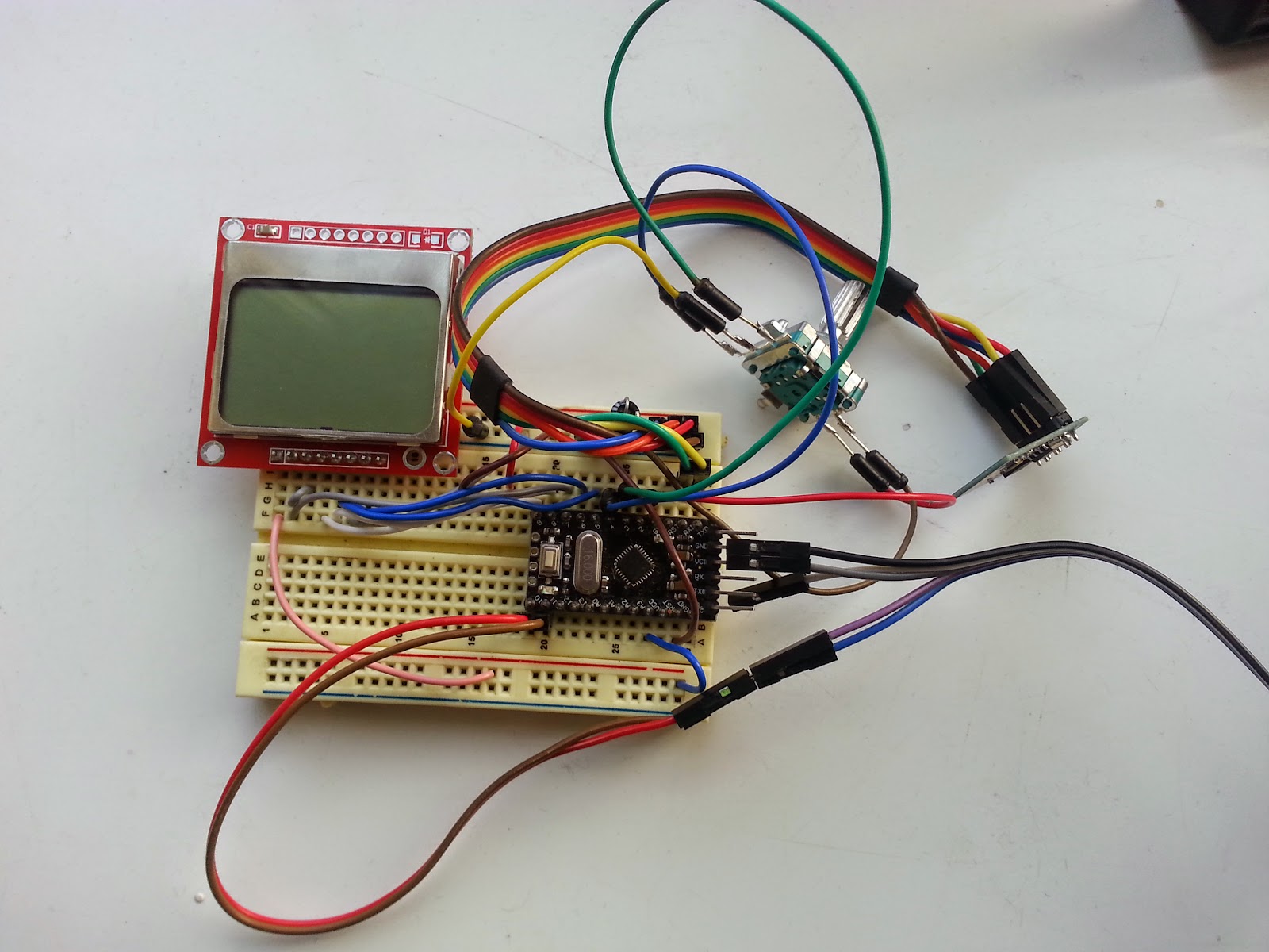
We've recently got re-acquainted with the old Nokia 5110 displays, so it made sense to build something around that for our unit. Originally we planned to have the wifi module list all available APs (access points) and allow the user to scroll through a list of them onscreen.


This idea worked fine, at the BuildBrighton Hackspace, where only three or four wifi access points are accessible from inside a big tin shed that acts like a large Faraday cage! Trying the same approach at home, where there can be ten or more available wifi hotspots at any one time, and the module couldn't cope.

We're assuming that the list of available wifi connections exceeded some string/character limit, and the wifi module simply fills up it's buffers trying to query every one in range - whatever the reason, using the AT+CWLAP command sometimes causes the wifi module to lock up.

What we needed was some way of entering an SSID and password, using the Nokia screen to display progress. Our imagined device would have only a few buttons, and a phone-text-style method of data entry could get a bit clumsy. It didn't take Steve long to suggest a menu-based interface and a rotary encoder for selecting letters/numbers/symbols from a pre-determined list of characters - a bit like when you used to put your initials on the high score table on the original Space Invaders arcade machines.

At first, a menu-based interface seemed like overkill - Steve loves everything to be aesthetically pleasing, we just like stuff to work! But his persistence paid dividends: despite making the firmware much more complicated than it was, the end result is an interface which is simple and intuitive to use. And more importantly, one that works!


(what's with the nasty jump in the video? Well, of course, I'm not going to publish my real wifi SSID and password on here - so I paused the video, entered the real username/password, and set the video recording again. Honestly, some people think you have to be an idiot to be in the Nerd Club!)

Surprisingly, the wifi modules retain their last connection details. We were anticipating having to store and retrieve SSID details to/from eeprom - but it turns out to be unnecessary. If you power down the wifi module, it will try to connect to the same source as last time, using the same SSID and password as before.

This makes our firmware quite a bit easier than we were expecting (once we got over Steve's extra complexity for the menu system). On boot up, we simply query our IP address, using the AT+CIFSR command, every 5-8 seconds. Once a connection has been established, we'll see an ip address in response to this command. If we get "error" or an empty string four times in succession, we move on to the "enter SSID "screen and prompt the user for their SSID and password.

Once these have been entered using the rotary encoder, we try again, four times. Setting the connection details using the AT+CWJAP command always returns OK - even if the password is incorrect and the connection failed. So we simply set the SSID/password combination, then query for a valid IP address, just as if the device had first switched on. If, after four attempts, there is no connection, we assume the connection details are incorrect, and prompt the user for their password again.

Once the wifi module has an IP address, we simply start it up as a server, using AT+CIPMUX=1 (to allow multiple clients to connect to it over the network) and then AT+CIPSERVER=1,port_number to start listening to incoming connections.

All in all, we're quite pleased with how far this has come.
The last stage is to get it all into a nice little enclosure and look like a "proper" wifi module - not just a homebrew circuit on a bit of home-etched PCB!

Game application testing

A little while back we were trying out some ideas for making a vector-based line-of-sight algorithm, in Flash/AS3. We spent a few hours this weekend turning a few scribbled ideas into a simple physics engine for calculating not just line-of-sight, but also for firing bullets with ricochet/rebounding off the walls.

  • The basic idea is that we draw a line between two points.
  • Then, loop through every line in the map, and see if the line we've just drawn intersects the line on the map. 
  • If it does, use pythagoras' equation to calculate the linear distance between the starting point and the point of contact.
  • If this distance is shorter than any previous collision point (it's quite possible that one, long line can intersect a number of points on the map) then we remember this point and continue testing the other lines in the map.
  • At the end of all this testing, if there's been a collision, we should have stored the first point along the line that meets with a wall. 


  • We then calculate the linear distance between the point of collision and the destination point. This represents the amount of travel "still to complete" after we ricochet/rebound off the wall.
  • The next thing to do is to calculate the potential destination point, after applying rebound at the point of contact.
  • The line-of-sight function is called a second time, with the starting point now the earlier collision point, and the end point the new, calculated destination point (after applying the rebound/ricochet function to the original line). This new line is then tested against every line in the map, and any more collisions calculated in the same manner.


(we marked each collision point on the map during testing)


For further testing, we overwrote the "recalculate distance after collision" routine, and made it a (large) fixed amount. This meant that every time the line-of-sight hit a wall in the map, it would always ricochet by a large amount - the idea being to test how it would react over a large distance.


It was to some relief that the ricochet/rebound algorithm correctly drew the expected path. It was noted at this point that the angle of rebound appears similar on every collision point. This is actually to be expected - since we're using only walls that are either vertical and horizontal, and our algorithm calculates a "perfect rebound" (the angle of approach is also the angle it leaves the collision point) it makes sense that we see the same angle throughout the whole screen.

Confident that the rebound function was working correctly, we started to add different functionality to different walls.


Using an online editor made earlier, we can describe our map as a number of "lines with properties" as an xml document. As shown in the image above, one of the properties that we can apply to our lines/walls is "can shoot through". Different lines with different properties can be used to describe different types of walls in our game maps.

For example, a line which can be "seen through" but not "can shoot through" could be used to indicate bullet-proof glass, or - in a sci-fi game - a force-field. Similarly, a line which the player "can shoot through" but not "see through" could be used to indicate a line of fog or smoke.

To further test our line-of-sight/bullet-path routines, we made one of the walls (specifically, in the image above, line 4) "passable" by setting "can shoot through" to "yes". The resulting test looked crazy - but after investigating a bit further, it actually appears to be correct too!


So we've tested our line-of-sight/bullet path routine with simple and complex paths, and proven that we can change the properties of different walls in the map, to alter the way the bullets ricochet and bounce around the map. It's starting to look like we've got the basis of a pretty impressive engine for our board game....


Finishing Space Marines the quick and easy way

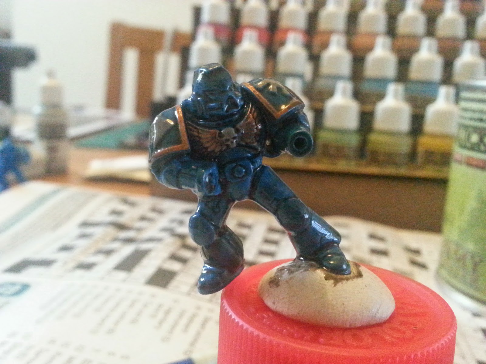
After sploshing some paint on half a dozen space marines, and coating with Army Painter's Dark Tone Quickshade, we had to wait 24 hours for the solvent based varnish to dry.

The miniatures actually looked pretty good (in the right lighting condtions) just as they were, albeit a bit shiny (ok, really, really shiny).


The dark tone provides really nice, deep contrasting shading, while the high points on the miniature are nice and bright. But the gloss finish is really unappealing (it doesn't show up too well in the photo, but it's really not nice at all!).

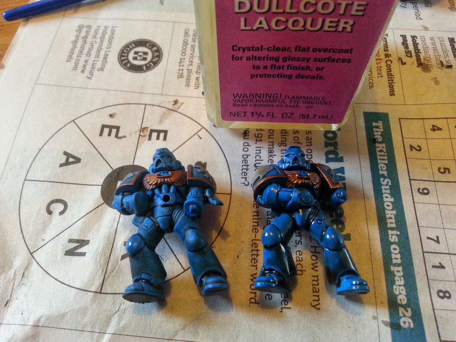
To tone down the gloss effect, we use Testor's Dullcote. It's a matt varnish, specially formulated to provide an ultra-matt surface. Some people even call it Deadcote - it does such a good job of "matting down" anything even vaguely shiny. (in comparison, the Army Painter Anti-shine - when you can get it to work - needs about two or three coats to completely remove the gloss shine created by the Quickshade). Dullcote takes just a couple of hours to dry fully, and provides a nice, matt surface which takes acrylic paints really well.


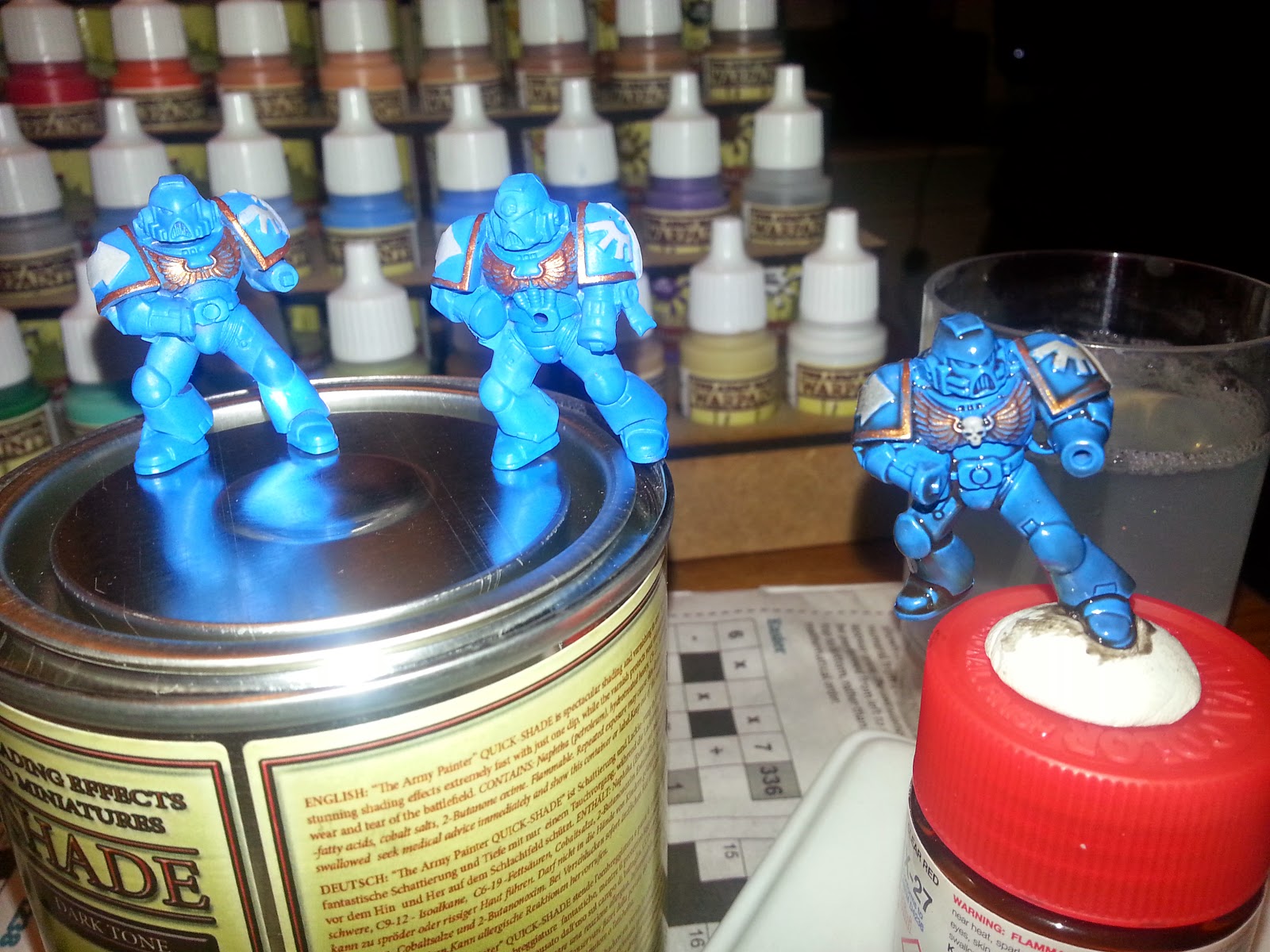
The character on the left has been painted with Dullcote, the character on the right is still waiting to be dulled down.

An interesting effect of applying dullcote is that it not only removes the shine from a model, but also does something to the contrast of the colours. The darkest recesses no longer appear really dark, and the raised parts no longer "stand out" because of their shiny appearance. It seems to not only dull the shine, but also the brilliance of the colours.


In the top half of the character on the left, you can see where the original Crystal Blue colour has been painted back in - particularly noticeable around the helmet and shoulder pads. Care was taken to allow a little of the "dulled" colours to show through (there'd be no point in completely painting over the lot of it!) and the result is a much "cleaner" looking model (compared to the model on the right).

Something that becomes noticeable after applying the Dullcote is how around many of the recesses, the paint actually appears brighter around the edges. Take a look at the markings on the bottom of the legs near the feet: the recessed part appears to be outlined in black - an affect we'd like to keep - but immediately alongside, the darkened-down blue appears much brighter than the surface around it.

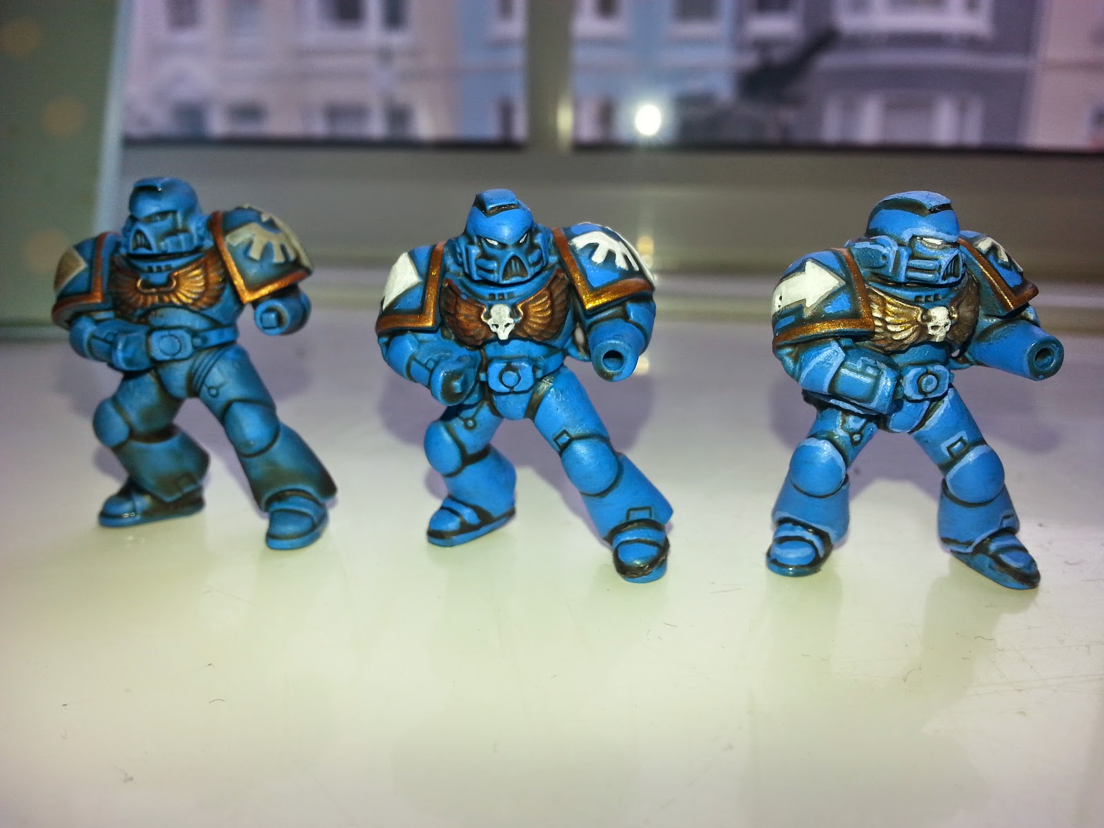
This is an affect we wanted to simulate, by applying a much brighter blue colour as "edge highlights". The transistion from dulled, to cleaned, to highlighted model is shown below.


(although up close, you can see some of the brushmarks where the highlight colours have been applied, at a distance of a couple of feet - the distance you'd expect them to be when on a board game playing area - the finished miniatures look great!)

The miniature on the left is fresh from being Dullcoted. The model in the middle has had large areas of colour repainted (the white on the shoulders, a brighter gold applied on the rimes, and the original Crystal Blue repainted over the larger exposed areas). The model on the right has been "edge highlighted" to pick out the edges and transitional parts: it's particularly noticeable on the elbow pads and around the helmet and feet.

At this point, we're going to call our miniatures done (the guns and backpacks obviously need applying, but we're done as far as painting goes). We could probably spend a number of hours on each one, picking out the tiny, minute details on the models, applying multiple layers of shading and highlighting and so on. But the whole point of this exercise was "speed painting" - to get some models painted up to a "good enough" standard to pu them onto the tabletop.

And we reckon the guy on the right is painted to a "good enough" standard for what we need.
Total time taken so far: 4.5hrs

Friday 14 November 2014

Motor controller with PIC using SLEEP and interrupt-on-change

With Real Life And Work (tm) being pretty traumatic over the last few weeks, it was nice to get away from it all and spend a few hours with not much planned, at BuildBrighton last night. As often happens, that's when things start to actually get done!

Steve's been working on an rather exciting firmware-update-over-audio idea: uploading Arduino "sketches" using squeaks and farts, rather like a ZX Spectrum used to do, back in the early 80s. It doesn't sound like much when written down, but the possibilities of such an approach are really quite exciting - maybe he'll expand more on it in the future.

In the meantime, Iain had asked for a simple project - a magnet controlled motor controller. We'd already got the PCB made up and the circuit working on a breadboard, so it was time to code up the firmware.


(note the use of a larger 640FET for the motor controller rather than a simple NPN transistor; the reason was two-fold - firstly, more current is available to the motor than if a wimpy 200mA 2N2222A were used and also, this particular FET also includes an internal fly-back diode which we need because we're switching an inductive load)


The actual functionality of the controller is pretty simple - present a magnet over a hall effect sensor, and start the motor running. Present the magnet a second time, and turn the motor off.  A two-stage state machine would easily take care of this. But there were a couple of other considerations that we had to take into account:

Firstly, he'd mentioned running a motor of a PP3 battery.
So we needed to make sure that our PIC microcontroller wasn't slurping all the power out of the battery, constantly polling the hall sensor on the input pin. This involves putting the PIC to sleep when not needed. Which means, of course, that we need to use some kind of wake-up interrupt to take it out of sleep.

Here's what we came up with:


Define CONFIG1 = 0x0984
Define CONFIG2 = 0x1cff

Define CLOCK_FREQUENCY = 1
AllDigital

symbols:

declarations:
     Dim state As Byte
     Dim timer_count As Word
     Dim i As Byte
   
     Symbol motor_output = PORTC.3
     Symbol magnet_in = PORTA.5
     Symbol led = PORTC.2
   
configpins:
     ConfigPin PORTA = Input
     ConfigPin PORTC = Output
     ConfigPin motor_output = Output
     ConfigPin magnet_in = Input
   
initialise:
     'internal oscillator defaults to 500khz internal
     WaitMs 100 'wait for internal voltages to settle
   
     'enable pull-up resistors on encoder pins, and pushbuttons
     OPTION.7 = 0 'wpuen=7
     WPUA = 0xff 'enable pull-ups on all portA
     state = 0
   
     timer_count = 0
     Low motor_output
     Low led
   
     'enable the interrupt on change register
     INTCON.IOCIE = 1
     IOCAN.5 = 1 'portA raised an interrupt on change
   
     'enable interrupts
     INTCON.GIE = 1
         
loop:
     Select Case state
                     
           Case 0
           'motor is not running
           If magnet_in = 0 Then
                 'debounce the input
                 WaitMs 10
                 If magnet_in = 0 Then
                       High motor_output
                       High led
                       WaitMs 200
                     
                       'wait for the magnet to be removed
                       While magnet_in = 0
                             'do nothing
                       Wend
                       state = 1
                 Endif
           Endif
         
           Case 1
           'motor is already running
           If magnet_in = 0 Then
                 'debounce the input
                 WaitMs 10
                 If magnet_in = 0 Then
                       Low motor_output
                       Low led
                       WaitMs 200
                     
                       'wait for the magnet to be removed
                       While magnet_in = 0
                             'do nothing
                       Wend
                       state = 0
                 Endif
           Endif
     EndSelect
   
     timer_count = timer_count + 1
     If timer_count > 5000 Then
           'testing: show the going to sleep sequence
           'For i = 1 To 3
           'High led
           'WaitMs 80
           'Low led
           'WaitMs 80
           'Next i
           timer_count = 0
           ASM: sleep
     Endif

Goto loop
End
                     
On Interrupt
     If IOCAF.5 = 1 Then
           'clear the interrupt
           IOCAF.5 = 0
           timer_count = 0
     Endif
Resume


The interesting things to note here are
a) the use of inline ASM. Oshonsoft as a compiler is great for just adding in some assembly language right in the middle of your basic code. Just use the tag ASM: and then your assembly instruction. One little gotcha to look out for is there must be a space or a tab between the ASM: statement and the command (otherwise the compiler treats the next word as a label, not an instruction)

b) the use of INTCON.IOCIE = 1 to enable interrupt-on-change. Combined with IOCAN.5 = 1 this means that when pin A5 goes low (the register to monitor rising edges on PORTA is called IOCAP) the interrupt-on-change interrupt is fired. Luckily for us, this interrupt can also bring the device out of a sleep state

c) although commented out, during testing we put a "shutdown" routine (flashed an LED a couple of times) to indicate when the device was going to go to sleep. This proved useful to demonstrate that the device was actually asleep (and that no activity was actually taking place). To see this in action, uncomment the shutdown flashing LED and comment out the ASM: SLEEP statement. You should see that the LED flashes then after a second or two delay, flashes again - this is the behaviour of the firmware. If you now re-enable the SLEEP statement, the LED only flashes once: the sleep statement has suspended the program execution (just as we hoped it would).

Of course, when using interrupt-on-change, it's important that other (unused) input pins are not accidentally firing the change-interrupt because they've been left floating. Although the IOCAN register masks out only the pins that are to be monitored, it doesn't hurt to ensure that the pull-up resistors are enabled on any input pins, just in case.

So there we have it, a quick and simple project made up over a few cups of teas and a few enjoyable hours talking rubbish with the other nerds. With the firmware written and tested, we'd better get this thing in the post so Iain can actually put it to use!


Speed painting Space Marines

Mention miniature board gaming, or even tabletop wargaming, and there's always the elephant-in-the-room that no-one wants to talk about: Games Workshop - and, more specifically, their Warhammer/Warhammer 40K range.

Our electronic board game has been designed specifically for anyone to play (eventually) any game, using any miniatures they like on it. So we've been and bought models from Hasslefree Miniatures, Heresey, Forlorn Hope, Black Scorpion and many other suppliers. We've quite a range of sci-fi, western and zombie miniatures (still looking for a half-decent human fantasy football team though!) but, to date, no Games Workshop/Warhammer miniatures of note (maybe the odd one here and there in a scraps box).

Now GW seem to be the Marmite of the gaming world - some people hate them, some people love them. At Nerd Towers, we're pretty ambivalent. They do make some very nice, detailed miniatures. But so do other suppliers. They do sell miniatures at eye-wateringly high prices. But so do some other miniature suppliers (particularly those based in mainland Europe). But there's no real reason why we've avoided GW - we just wanted to be able to show that our gaming system would work with any miniatures, and so have mostly been using non-GW models.

But our gaming system is for any miniatures. And that also means with GW miniatures too. So we recently bought some of the most famous GW characters on the market - half a dozen Space Marines - from eBay and set about painting.

At this stage in the project, we just want models that will sit on the board game and look half-decent to demonstrate the games. We're not looking to create the next Golden Demon Masterpiece, with masses of detail, and lots of technically brillant artwork. Just something to paint (relatively) quickly. Here's how we've painted our Space Marines so far:

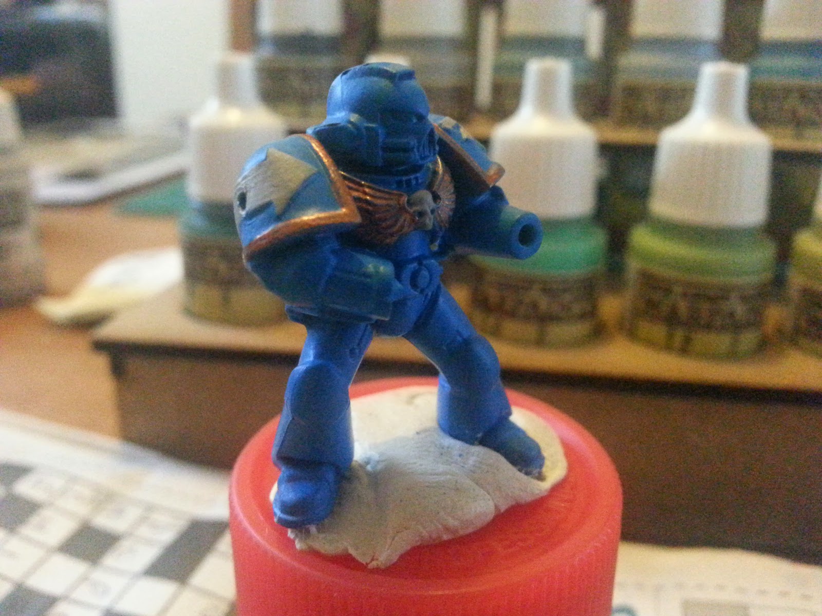
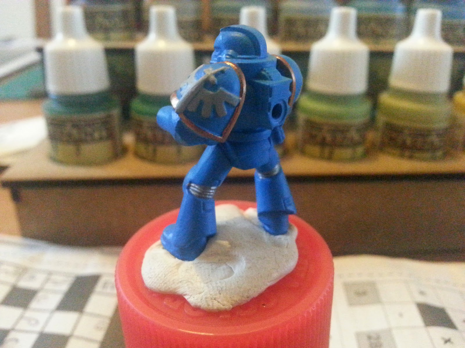
Firstly, we sprayed half a dozen marines with the Army Painter primer/base coat spray. This stuff is brilliant - it gets you a nice, solid, vibrant coloured base to work from. Because we'll be using the Army Painter Strong Shade (the black version of their Quickshade product), we went with a much brighter blue than we're expecting to end up with.

The spray paint is called Crystal Blue.


(after spraying the Space Marines, we also sprayed some Tyranid aliens for them to fight against, in the boardgame - more on those in a later post)

Because we're speed painting - deliberately aiming to get a squad of six characters onto the tabletop as quickly as possible - we kept the detail painting to a minimum. After these characters have been Quickshaded (is that even a verb?) and DullCoted (ditto?) we'll spend a bit of time with a small paintbrush, picking out some of the tiny details. For now, we're going for overall effect.


We stuck to just three additional colours on the marines. The bits that will eventually end up white were painted with a pale Ash Grey and the bits that will eventually be gold picked out with Golden Bronze. Normally with metals, we'd paint them black then drybrush with the metallic colour. Because our black is going over the top (almost like an inkwash) we painted the metal straight over the blue base coat. It didn't cover as well as it would have over black - but that's ok; it'll get another coat after the dullcote/matt varnish later anyway.


On the backs of the legs and where armour plates joined, we painted Platemail Silver. As with the bronze, normally we'd paint these black and drybrush, but we're going to flood the entire miniature in Quickshade in a moment....


The Quickshade (Dark Tone) really darkened the miniature down a lot (which is why we went with such a bright blue in the first place). We'd already got some Strong Tone from previous experimenting, but it does tend to leave a brown-y tinge on the miniatures. On miniatures based in red/green colours, this looks fine. On blue/grey colours, it can look a bit muddy or dirty - so we tried the black-based Dark Tone on our blue marines (we'll be going back to the browny Strong Tone for the aliens, so maybe the two will give contrasting effects?).

 Quickshade needs about 24 hours to go off fully (painting over it too early with matt varnish to dull the shine will cause it to react and bubble and peel, so always allow at least 24 hours to dry fully).


Here's a quick comparison between the Quickshade coated and non-Quickshaded miniatures. Note how the shaded character appears to have much more definition already!

Total time spent on six Space Marines: 2hrs
Total time remaining: who knows?!


Monday 3 November 2014

Cheap Chinese laser cutter

Grumpy Paul was in the market for a laser cutter.
We've been reading mixed reviews about the cheap chinese laser cutters coming out of China; most say they're rubbish and should be avoided. But every now and again, someone will strip one down, reassemble it and conclude that, with a bit of care and effort, they can be made into half-decent machines.

We've been watching them on eBay for a few months now.
A while back there were a few available for about £350. That seemed a pretty good price, compared to the £1200+VAT we paid HPC for our laser a few years ago (HPC customers in recent years have complained about their lack of support, and their latest machines just look more and more like cheap chinese machines re-sprayed red and cream).

Then they'd all disappear off eBay and nothing would be available for under about £550 plus delivery. For the last few weeks, cheap laser cutters have been few and far between on both eBay and Amazon.

Recently (as in, a few days ago recently) quite a few appeared on eBay for the princely sum of £280. This seemed too good to pass up on - even if they're a bit of a gamble, so collectively a few of us clubbed together to try one out.

Bang! The trigger was pulled on Thursday.
On Saturday, a massive box turned up at Nerd Towers. A few hours later, and it was setup in Grumpy Paul's flat. They certainly didn't mess about with the amount of bubble wrap!


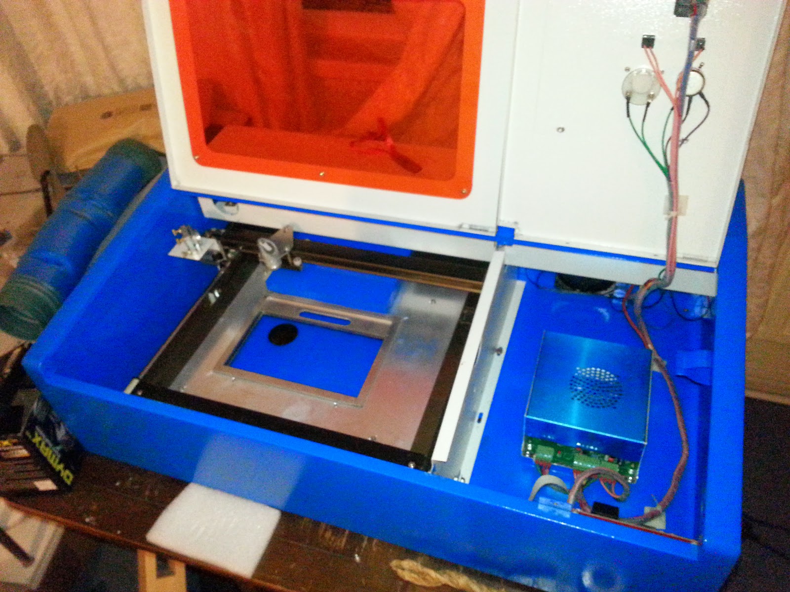
The machine is definitely not a high-end cutter. But the quality of the assembly was surprisingly not-too-bad-for-a-cheap-chinese-machine.


Unlike many people who've had these machines, there were no loose wires or badly crimped connectors


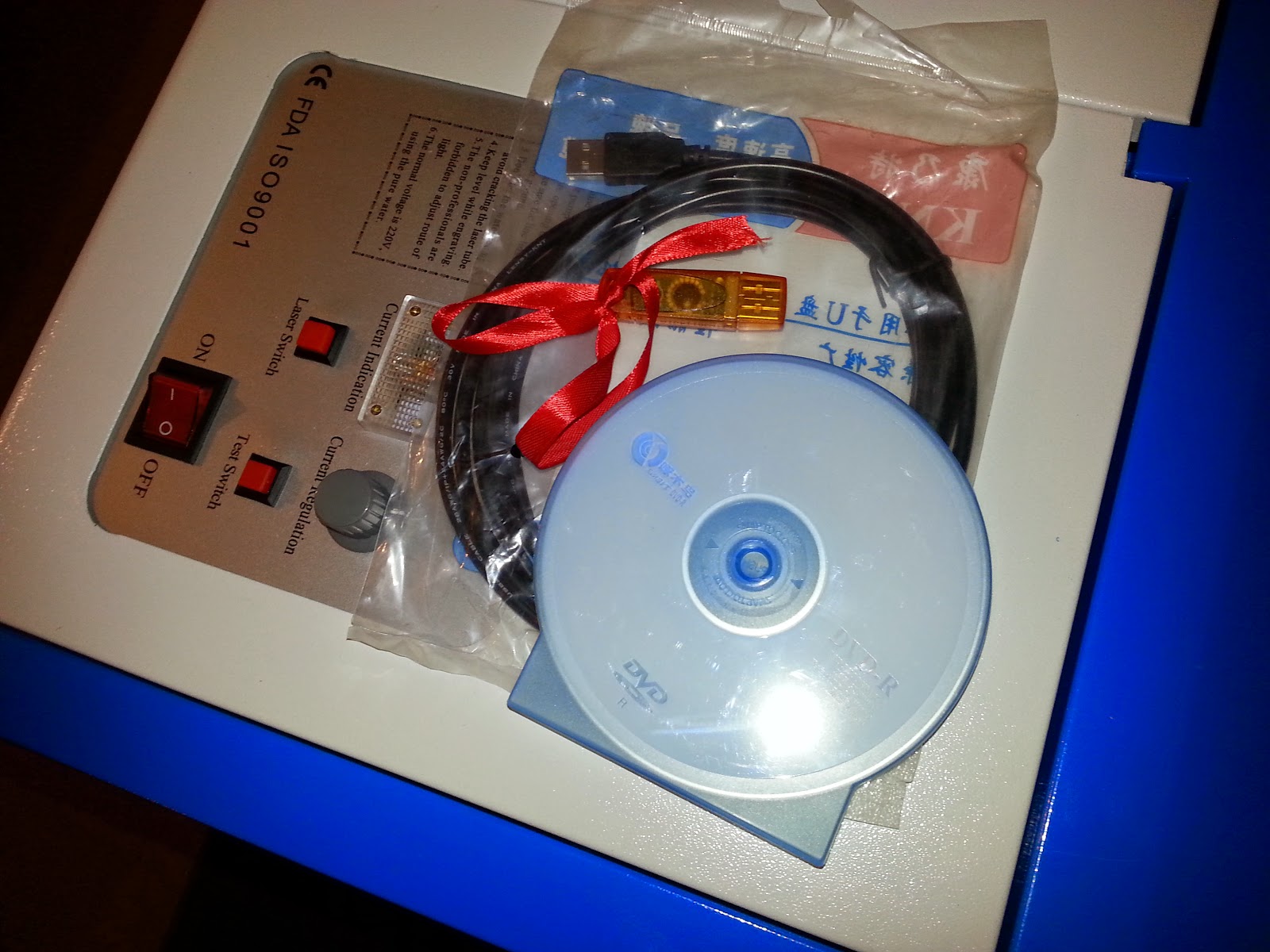
The MoshiDraw software and hardware dongle looked decidedly "eBay"


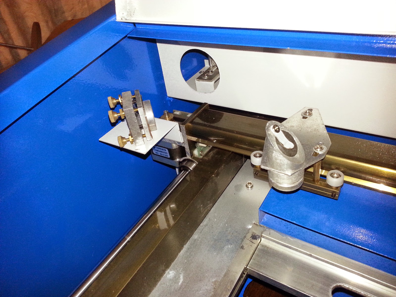
There's no air assist, or red dot on the cutting head. These can be retro-fitted, once the machine is up and running, but it also means that there's no cable-chain running on the x-axis (luckily, Martin Raynsford posted some plans for one he built a little while back)


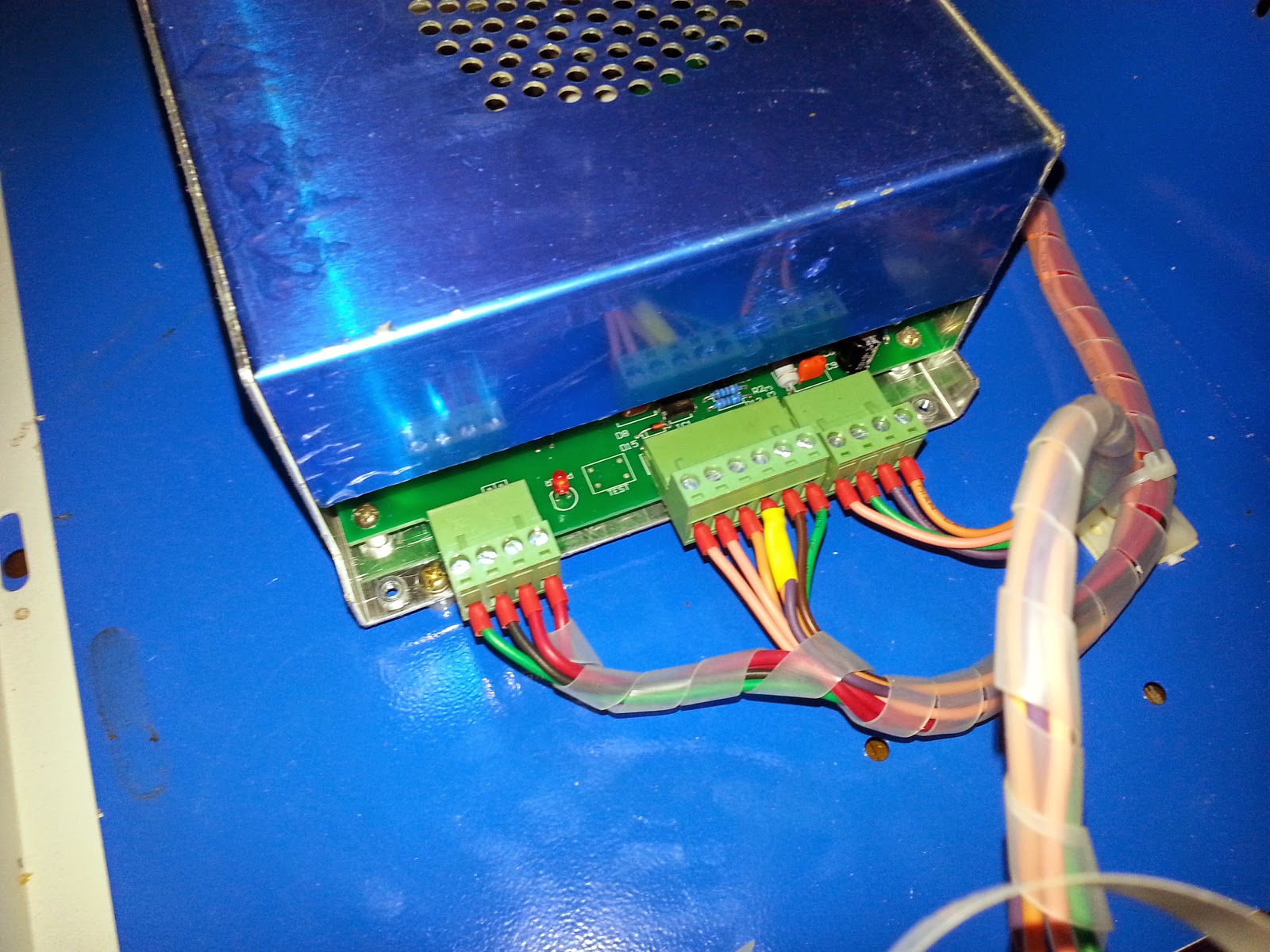
The MoshiDraw software installed easily enough onto a Windows XP machine, so it was soon time to fire up the laser and try it out. First things first, connect up the water pump and give it a whirl.


After about twenty minutes, there were still massive air bubbles in the water jacket. On our HPC machine, any (small) bubbles usually clear after just a few minutes of running, or by tipping the machine and pinching the inlet water pipe quickly.

Trying the same techniques on this machine made no difference. There was a large, continuous air bubble in the top third of the entire length of the glass tube.

Robot-Laser-Steve (who has experience of dismantling and re-building at least three laser cutters) suggested that maybe the pump wasn't powerful enough to clear what had effectively become an airlock in the top of the tube.

We tried tipping the laser cutter up onto one end, to get all the air into one end of the tube. At this point, the problem became apparent:


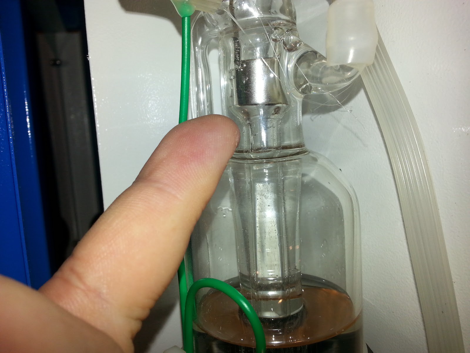
The neck of the laser part of the tube (inside the outer glass tube) had cracked. Even after forcing the tube to fill a bit more (by pinching the outlet pipe closed for a few seconds at a time, to force some of the air bubbles out) the problem looked irreparable.


 The photo above shows the inner tube leaking, as the outer jacket fills with water.
No lasering would be going on this weekend!

To be fair to the sellers, the problem was pointed out and they immediately sent out a replacement tube. Although this isn't something we were planning on fitting ourselves, if it means that Mr Grumpfire can get lasering for under £300, it'd still be great purchase.

If the replacement tube doesn't work, however (or arrives damaged as well) the whole lot can go back and we'll ask Mr eBay for a full refund. It'll probably be a few days yet before anything actually gets done - one of us is at the other end of the country, one of us is waiting for a baby to pop out any day now, and one of us has no idea what they're doing. We'll leave it to the reader to decide which is which!

Farnell does it again

We ordered a load of atmega128 chips from Farnell the other day, after discovering we'd been sold a load of dodgy clones off AliExpress a while back.

The order arrived, albeit two chips short, and we set about soldering them up onto our pro-manufactured boards. Instantly, the programmer recognised them, and we managed to burn some new firmware onto them - result!

It was only when a massive box turned up at the weekend, we tried to review past Farnell orders, to see what else was on back order. The box was so big it had to be delivered via courier, no less!


Surely Farnell wouldn't be so crazy as to send two little tiny microcontrollers in such a massive box? So what was inside?


Wow.
Well done, Farnell. You've outdone yourself this time!