Saturday 31 January 2015

Temperature controller for K-type thermocouple and MAX6675

After CNCPaul/LathePaul created such an awesome-looking heating chamber, the postie once again knocked on the door at Nerd Towers to deliver yet another eBay purchase - this time, it was a K-type thermistor and breakout module (basically just a MAX6675 on a board with pin headers)

We  had looked online at temperature controllers but they all seemed to be quite pricey for what they were - a cheap thermistor, a few 4x7 segment displays and a fancy box. Since we've currently got loads of 16x2 character displays and a boxful of PIC microcontrollers knocking about, it made sense (to us at least) to make our own temperature controller with a simple menu system.


We stuck an HD44780 character display onto a breadboard with a massive old PIC16F877A chip that just happened to be lying around. To this we also added the newly acquired temperature module and bundled some firmware onto the chip.

The LED on this breadboard indicates whether or not a relay would be activated, to switch the mains supply to our 300W cartridge heaters. As our target temperature in this example has yet to be met, the heater element is still switched on.

Here's the firmware for our controller. It's pretty basic. The most notable thing about it are the button press routines - we're using just three buttons, up/down/select. But, like an alarm clock, a "short press" will cause the values to increase/decrease by just one at a time, but a "long press" results in the numbers whizzing by in multiples of ten.

Define CONFIG = 0x3f32
Define CLOCK_FREQUENCY = 20
Define STRING_MAX_LENGTH = 30

AllDigital

definitions:
     Define LCD_BITS = 4 'no of pins to connect to character LCD
     Define LCD_DREG = PORTD '4-pin interface on this port
     Define LCD_DBIT = 4 '4-pin interface is on (0=0-3, 4=4-7)
     Define LCD_RSREG = PORTD
     Define LCD_RSBIT = 2
     Define LCD_EREG = PORTD
     Define LCD_EBIT = 3
     Define LCD_RWREG = PORTD
     Define LCD_RWBIT = 1

     Define SPI_CS_REG = PORTC
     Define SPI_CS_BIT = 1
     Define SPI_SCK_REG = PORTC
     Define SPI_SCK_BIT = 0
     Define SPI_SDI_REG = PORTC
     Define SPI_SDI_BIT = 2
     Define SPI_SDO_REG = PORTC
     Define SPI_SDO_BIT = 3
     Define SPICLOCK_STRETCH = 9

     Symbol led_pin = PORTA.0
     Symbol led_heater = PORTA.1
     Symbol heater_relay = PORTA.2
     Symbol button_up = PORTB.0
     Symbol button_down = PORTB.1
     Symbol button_ok = PORTB.2

     Symbol spi_sck = PORTC.0
     Symbol spi_cs = PORTC.1
     Symbol spi_si = PORTC.2
   
     ConfigPin PORTD = Output
     ConfigPin PORTB = Input
     ConfigPin led_pin = Output
     ConfigPin led_heater = Output
     ConfigPin heater_relay = Output
   
     ConfigPin spi_sck = Output
     ConfigPin spi_cs = Output
     ConfigPin spi_si = Input
   
     Dim state As Byte
     Dim return_state As Byte
   
     Dim b As Byte
     Dim target_temp As Word
     Dim current_temp As Word
     Dim tmp_temp As Word
     Dim overshoot As Word
     Dim last_temp As Word
     Dim temp_direction As Bit
     Dim button_press_count As Byte
               
initialise:

     SPIPrepare 'prepare the software SPI interface
     OPTION_REG.7 = 0 'enable pullups on portb (/RBPU)
     Lcdinit 0 'no cursor on the lcd display
     Low led_heater 'make sure we boot up with the heater off
     Low heater_relay 'heater indicator is off
   
     state = 0
     overshoot = 0
     temp_direction = 0
         
     SPIPrepare
     High spi_cs
     Low spi_sck
   
loop:
     Select Case state
           Case 0 'first boot up
           Lcdcmdout LcdClear
           Lcdout "Temperature"
           Lcdcmdout LcdLine2Home
           Lcdout "Controller"
         
           'read the last set temperature value (we'll automatically go back to this)
           Read 2, b
           target_temp.LB = b
           Read 3, b
           target_temp.HB = b
                     
           If target_temp.LB = 0xff And target_temp.HB = 0xff Then
                 'we've just read two blank values from eeprom, so choose
                 'any old default value - why not aim for, say, 100?
                 target_temp = 100
           Endif
         
           'read the last set overshoot value
           Read 4, b
           overshoot.LB = b
           Read 5, b
           overshoot.HB = b
         
           If overshoot.LB = 0xff And overshoot.HB = 0xff Then
                 'we've just read two blank values from eeprom, so choose
                 'any old default value - why not, say, ten?
                 overshoot = 10
           Endif
         
           'read the last overshoot value from eeprom (this is how many degrees before
           'reaching target temp we need to shut off for, to allow for overshooting)
         
           WaitMs 1000
           state = 1
         
           Case 1 'show the target and current temperature(s)
           Gosub get_current_temp
           Lcdcmdout LcdClear
           Lcdout "Target temp: "
           If target_temp < 100 Then Lcdout " "
           If target_temp < 10 Then Lcdout " "
           Lcdout #target_temp
         
           Lcdcmdout LcdLine2Home
           Lcdout "Actual temp: "
           If current_temp < 100 Then Lcdout " "
           If current_temp < 10 Then Lcdout " "
           Lcdout #current_temp
           state = 2
         
         
           Case 2 'monitor the current temp and the target temp
           Gosub get_current_temp
           Lcdcmdout LcdLine2Home
           If current_temp = 999 Then
                 'something has gone wrong
                 Low heater_relay
                 Low led_heater
                 Lcdout "**** ERROR! ****"
               
           Else
                 If current_temp <> last_temp Then
                       Lcdout "Actual temp: "
                       If current_temp < 100 Then Lcdout " "
                       If current_temp < 10 Then Lcdout " "
                       Lcdout #current_temp
                 Endif
                           
                 If last_temp <= current_temp Then
                       'temperature is rising
                       temp_direction = 1
                 Else
                       'temperature is falling
                       temp_direction = 0
                 Endif

                 If current_temp > target_temp Then
                       'we're over the target temperature so shut the heaters off
                       Low heater_relay
                       Low led_heater
                 Else
                       If temp_direction = 1 Then
                             'while the temperature is rising, we want to keep the heaters on
                             'until we cross the threshold of (target_temp-overshoot_value)
                             'and then turn them off and allow the block to continue heating
                             'even for a very short time
                             tmp_temp = target_temp - overshoot
                             If current_temp > tmp_temp Then
                                   'threshold exceeded, turn off the heater(s)
                                   Low led_heater
                                   Low heater_relay
                             Else
                                   'still not quite there, keep the heaters on
                                   High led_heater
                                   High heater_relay
                             Endif
                       Else
                             'if the temperature is falling, the bottom threshold
                             'is our target temperature minus the overshoot value; once we
                             'fall below that, turn the heaters back on
                             tmp_temp = target_temp - overshoot
                             If current_temp < tmp_temp Then
                                   'we've cooled down too much, turn the heaters on again
                                   High heater_relay
                                   High led_heater
                             Else
                                   'we're cooling down, but are still pretty close to the target
                                   'temperature, so allow a little more cooling
                                   Low heater_relay
                                   Low led_heater
                             Endif
                       Endif
                 Endif
         
                 last_temp = current_temp
           Endif
         
           'now while the temperature is being monitored, check for button presses
           '(on a button press, turn off the heater(s) just for good measure, and
           'go to a new state just for handling changing the settings
           If button_up = 0 Or button_down = 0 Or button_ok = 0 Then
                 Low heater_relay
                 Low led_heater
                 WaitMs 50
               
                 While button_up = 0 Or button_down = 0 Or button_ok = 0
                       'wait for the button to be released
                       WaitMs 50
                 Wend
                 state = 3
           Endif
           WaitMs 1000
         
         
           Case 3 'press buttons to change menu option
           Lcdcmdout LcdClear
           Lcdout "> Change target"
           Lcdcmdout LcdLine2Home
           Lcdout " Edit overshoot"
           state = 4
         
         
           Case 4
           If button_up = 0 Or button_down = 0 Then
                 WaitMs 50
                 While button_up = 0 Or button_down = 0
                       'wait for the button to be released
                       WaitMs 50
                 Wend
                 state = 5
           Endif
           If button_ok = 0 Then
                 'debounce the button press
                 WaitMs 50
                 While button_ok = 0
                       WaitMs 50
                 Wend
                 state = 10
           Endif
         
           Case 5 'press buttons to change menu option
           Lcdcmdout LcdClear
           Lcdout " Change target"
           Lcdcmdout LcdLine2Home
           Lcdout "> Edit overshoot"
           state = 6
         
         
           Case 6
           If button_up = 0 Or button_down = 0 Then
                 WaitMs 50
                 While button_up = 0 Or button_down = 0
                       'wait for the button to be released
                       WaitMs 50
                 Wend
                 state = 3
           Endif
           If button_ok = 0 Then
                 'debounce the button press
                 WaitMs 50
                 While button_ok = 0
                       WaitMs 50
                 Wend
                 state = 11
           Endif


           Case 10 'change the target temperature value
           Gosub show_target_temp
           return_state = 10
           state = 12
         
         
           Case 11 'change the overshoot value
           Gosub show_overshoot
           return_state = 11
           state = 12

         
           Case 12 'button presses to alter target temperature/overshoot value
           If button_up = 0 Then
                 WaitMs 50
                 button_press_count = 0
                 While button_up = 0
                       'wait for the button to be released
                       button_press_count = button_press_count + 1
                       WaitMs 100
                       If button_press_count >= 5 Then
                             'this is a "long press" so increase the value by 10 every loop
                             If return_state = 10 Then
                                   target_temp = target_temp + 10
                                   If target_temp > 500 Then target_temp = 500
                                   target_temp = target_temp / 10
                                   target_temp = target_temp * 10
                                   Gosub show_target_temp
                             Endif
                             If return_state = 11 Then
                                   overshoot = overshoot + 10
                                   If overshoot > 500 Then overshoot = 500
                                   overshoot = overshoot / 10
                                   overshoot = overshoot * 10
                                   If overshoot >= target_temp Then overshoot = target_temp - 1
                                   Gosub show_overshoot
                             Endif
                             WaitMs 200
                             'stop the counter from rolling over
                             button_press_count = 5
                       Endif
                 Wend
                 If button_press_count < 5 Then
                       'this is a "short" press so increase the value by just one
                       If return_state = 10 Then target_temp = target_temp + 1
                       If return_state = 11 Then overshoot = overshoot + 1
                 Endif
               
                 If target_temp > 500 Then target_temp = 500
                 If overshoot > 500 Then overshoot = 500
                 If overshoot >= target_temp Then overshoot = target_temp - 1
                 state = return_state
           Endif
         
         
           If button_down = 0 Then
                 WaitMs 50
                 button_press_count = 0
                 While button_down = 0
                       'wait for the button to be released
                       button_press_count = button_press_count + 1
                       WaitMs 100
                       If button_press_count >= 5 Then
                             'this is a "long press" so decrease the value by 10 every loop
                             If return_state = 10 Then
                                   b = target_temp Mod 10
                                   If b = 0 Then
                                         If target_temp > 10 Then target_temp = target_temp - 10 Else target_temp = 0
                                   Else
                                         target_temp = target_temp / 10
                                         target_temp = target_temp * 10
                                   Endif
                                   Gosub show_target_temp
                             Endif
                             If return_state = 11 Then
                                   b = overshoot Mod 10
                                   If b = 0 Then
                                         If overshoot > 10 Then overshoot = overshoot - 10 Else overshoot = 0
                                   Else
                                         overshoot = overshoot / 10
                                         overshoot = overshoot * 10
                                   Endif
                                   Gosub show_overshoot
                             Endif
                             WaitMs 200
                             'stop the counter from rolling over
                             button_press_count = 5
                       Endif
                 Wend
                 If button_press_count < 5 Then
                       'this is a "short" press so increase the value by just one
                       If return_state = 10 Then
                             If target_temp > 1 Then target_temp = target_temp - 1 Else target_temp = 0
                       Endif
                       If return_state = 11 Then
                             If overshoot > 1 Then overshoot = overshoot - 1 Else overshoot = 0
                       Endif
                 Endif

                 state = return_state
           Endif
         
           If button_ok = 0 Then
                 WaitMs 50 'simple debounce
                 While button_ok = 0
                       'wait for button to be released
                 Wend
                 If return_state = 10 Then
                       'write the new target temp to eeprom
                       b = target_temp.LB
                       Write 2, b
                       b = target_temp.HB
                       Write 3, b
                 Else
                       'write the new overshoot value to eeprom
                       b = overshoot.LB
                       Write 4, b
                       b = overshoot.HB
                       Write 5, b
                 Endif
                 state = 1
           Endif

     EndSelect
Goto loop
End


get_current_temp:
     'read the value from the thermistor
     'in some libraries, they suggest performing a "dummy read"
     'to force the device to re-sample the temperature
     Low spi_cs
     WaitMs 2
     High spi_cs
     WaitMs 220
     'the device should now have a new temperature in it's buffer
   
     'enable CS so we can read data back from the device
     SPICSOn
     'give the device time to settle
     WaitMs 50
   
     'get the data as two bytes
     SPIReceive b
     current_temp.HB = b
     SPIReceive b
     current_temp.LB = b

     SPICSOff
         
     'now according to the datasheet, bit 15 is a dummy, bits 0-2 are status
     'so the actual temperature we need is in bits 14-3
   
     b = current_temp.LB
     b = b And 00000100b
     If b > 0 Then
           'bit 2 is normally low, and goes high when the thermistor is not connected
           current_temp = 999
     Else
           'bit-shift three places to the right
           current_temp = ShiftRight(current_temp, 3)
           'and mask out to get only the lower 12 bits
           current_temp = current_temp And 0x0fff
     Endif
   
     If current_temp = 0 Or current_temp = 0x0fff Then
           'something has gone wrong here
           current_temp = 999
     Else
           'the temperature reported has a resolution of 0.25 deg C
           'so we need to divide our final answer by 4 (or multiply by 0.25)
           'to get the actual temperature in degrees
           current_temp = current_temp / 4
     Endif
   
Return


show_target_temp:
     Lcdcmdout LcdClear
     Lcdout "Target temp: "
     If target_temp < 100 Then Lcdout " "
     If target_temp < 10 Then Lcdout " "
     Lcdout #target_temp
Return


show_overshoot:
     Lcdcmdout LcdClear
     Lcdout "Overshoot: "
     If target_temp < 100 Then Lcdout " "
     If target_temp < 10 Then Lcdout " "
     Lcdout #overshoot
Return

Our firmware allows the user to press a couple of buttons to change two different parameters:
Firstly, and most obviously, the target temperature to reach. When this is connected up, we're expecting to heat up a block of aluminium. The basic idea is to take a temperature reading and if we're below a certain threshold, turn the heaters on, until the block is "up to temperature"

We also added in another user-defined parameter: something we've called "overshoot".
This is because it's quite possible - as sometimes happens with heated elements like soldering irons for example - that the target temperature is exceeded. By how much can sometimes be predicted, so our variable "overshoot" means that the heaters will cut out a little bit before the ideal temperature has been reached.

So if the temperature of the block continues to rise, even when the heater(s) are turned off, it should - ideally - only reach, and not exceed, the target temperature.

We also use the "overshoot" value for monitoring a falling temperature, to give us a "safe zone" during which the heaters remain inactive. If we simply said "if the temperature is below this threshold, turn on the heaters" it's quite possible that the heaters will come on for a second or two, the temperature could rise by a single degree and the heaters get turned off - a few seconds later, the temperature drops a little, and the heaters are fired up again.

To avoid this "bouncing around" on a single value, our overshoot parameter allows us a "safety zone" of, say, 10 degrees (the user can make this wider or narrower as required). If our target temperature is 180 degrees, and our overshoot value is 10, this means:

When we first switch on, the heaters come on.
The heaters stay on until the temperature has climbed to 170 degrees.
When 170 degrees is exceeded, the heaters are turned off.
The temperature can continue to climb (if it climbs too high - i.e. the target temperature has been overshot by a long way, the user can edit the overshoot parameter to make it a larger value)
Eventually the temperature of the block will start to fall. Even if it falls below 180 degrees, we don't yet switch on the heaters
When the temperature of the block has fallen below 170 degrees (our target value minus the overshoot value)  and the temperature is falling, we turn the heaters back on.

By monitoring the "direction" of the temperature (either rising or falling) and by switching the heaters off slightly before the target temperature is reached, we should be able to maintain a fairly stable temperature in our heater block.

During testing, everything appeared to work as it should - immerse the thermistor into a cup of cold water and the temperature fell sharply. At the same time, the heater LED indicator lit up. We set our target temperature quite low (28 degrees) and our overshoot value to just 3 degrees, then held the thermistor in a closed fist.

The temperature continued to rise and at 25 degrees (three degrees before the target temperature) the heater indicator went out. After releasing the probe, the temperature continued to fall to ambient room temperature (and as the temperature fell below 25, the heater indicator once again came on to show that the heaters would normally have been activated).

Next time we're at the space, we should be able to drill and tap a small hole for the thermistor to be embedded into the heater block (hopefully avoiding drilling all the way through to the main chamber)  mount a relay in place of/as well as our heater indicator LED, and actually try our temperature controller out for real!


Friday 30 January 2015

Heating chamber for injection moulding

Last night was BuildBrighton once again, and this time I took our CNC machine along, to have a go at milling some of the material samples that arrived the other day.

Whenever anyone mentions CNC milling, CNCPaul bangs on about getting a decent spindle and things like runout and tolerances of 0.01mm and all that. Of course, when you're building a CNC machine yourself, the most important thing is getting the frame right, and getting it to move accurately. For any homebrew application, sticking a Dremel drill onto the z-axis is probably good enough.

This may be the case - but when you've got all that working, and you're cutting shapes with a 1mm bit, aiming for sub-millimetre accuracy, then it turns out that CNCPaul is absolutely right - the spindle is a pretty critical part of the machine! There's no point being able to place the cutting head to within 0.1mm only for it to gouge out a 1mm trench, 3mm wide!

If the milling bit is perfectly centred, and only rotates perfectly vertical, a 1mm bit creates a 1mm wide cut. But if the bit is even slightly off-centre, or slightly off-vertical, the cutting end of the bit follows a circular path on the end of a cone, and creates a much wider cut than required.

Unfortunately, our Dremel clone that is clamped to the CNC has a serious problem with runout. When the spindle turns, you can visibly see that the end of the cutting bit is drawing a rather wide arc, rather than simply spinning. We tried swapping out the collets, using different bits (in case either of these was bent) and packing the non-cutting end of the bit so that it couldn't wobble about (and cause the cutting end to move off-centre) but nothing worked. 

It seems that the Dremel clone in our CNC is simply not up to the job. We'll have to find an alternative - or maybe even follow CNCPaul's advice and invest in a half-decent cutting spindle!

However, just before setting off for the BuildBrighton Open Night, a parcel arrived, containing two cartridge heaters. Talk about fast service! So I took those along too, and CNCPaul brought along a lump of aluminium block he had knocking around going spare. A perfect opportunity to start on a heater block for an injection moulding machine.

The first thing to do was to cut off a section of aluminium block. We stuck with our original design and went for a 2" square block.


The bandsaw took forever to cut through the block, as the blade had about a million teeth per inch. Plenty of cooling lubricant didn't seem to do much. And after the blade got about half-way through, it started to veer outwards, producing a rather peculiar profile shape to our block. It wasn't exactly perfect, but it would have to do!


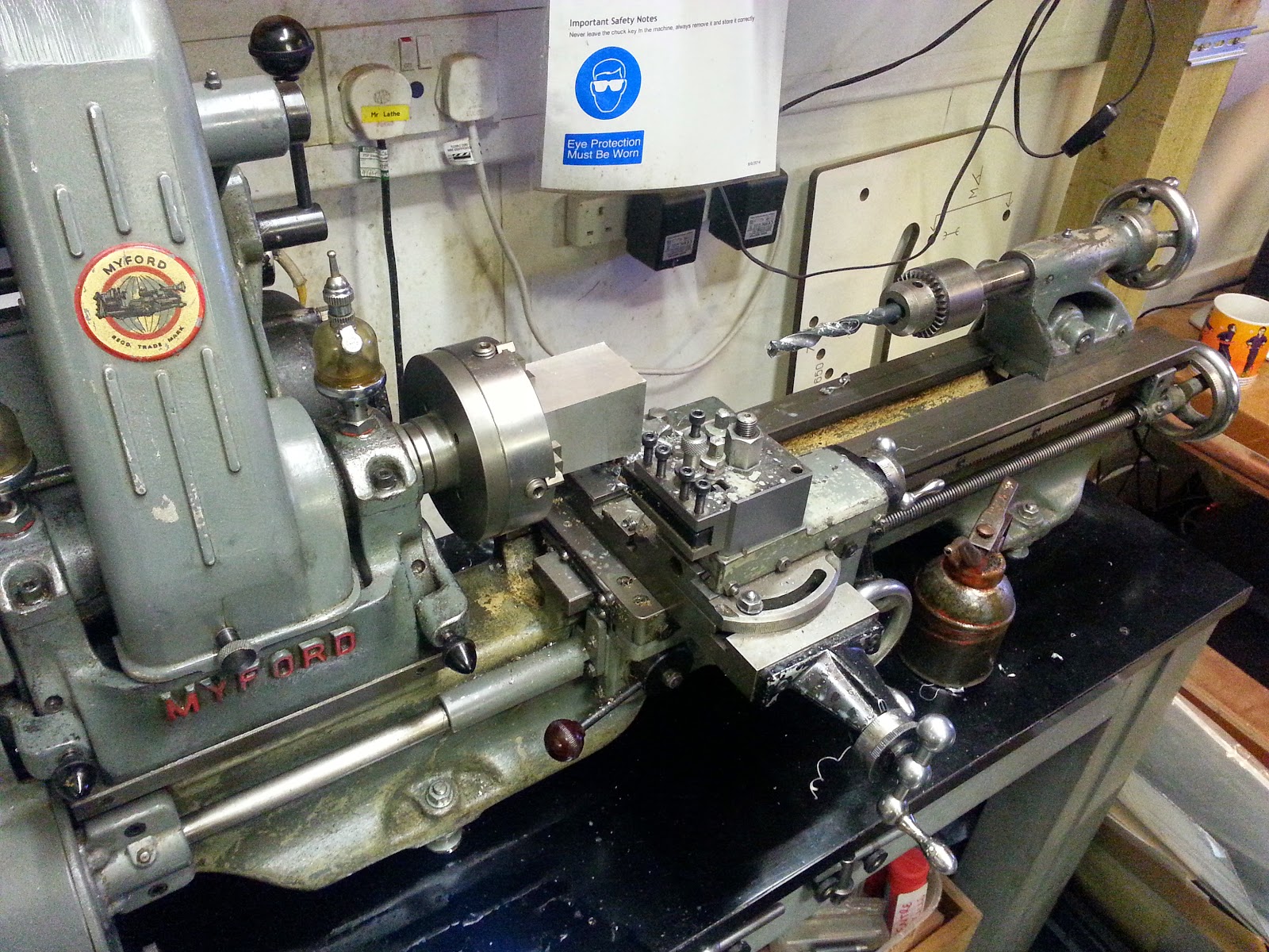
Then Paul got the block onto the Myford lathe and drilled out the centre hole for the chamber. This involved drilling with a 7mm bit to create the initial cavity, then expanding this using a 13mm bit - the largest metal cutting bit available at the workshop. Paul then used a boring tool, to open this cavity to about an inch in diameter.

Having discussed how important getting a drill/cutting bit perfectly vertical for any kind of drilling or milling application, it was ironic that the pillar drill in the workshop was so reluctant to drill - even a small pilot hole - exactly where we wanted it. With Jake's help and a lot of piling blocks under the piece to get it to drill far enough into the aluminium, we eventually managed to get the heating element holes drilled too.

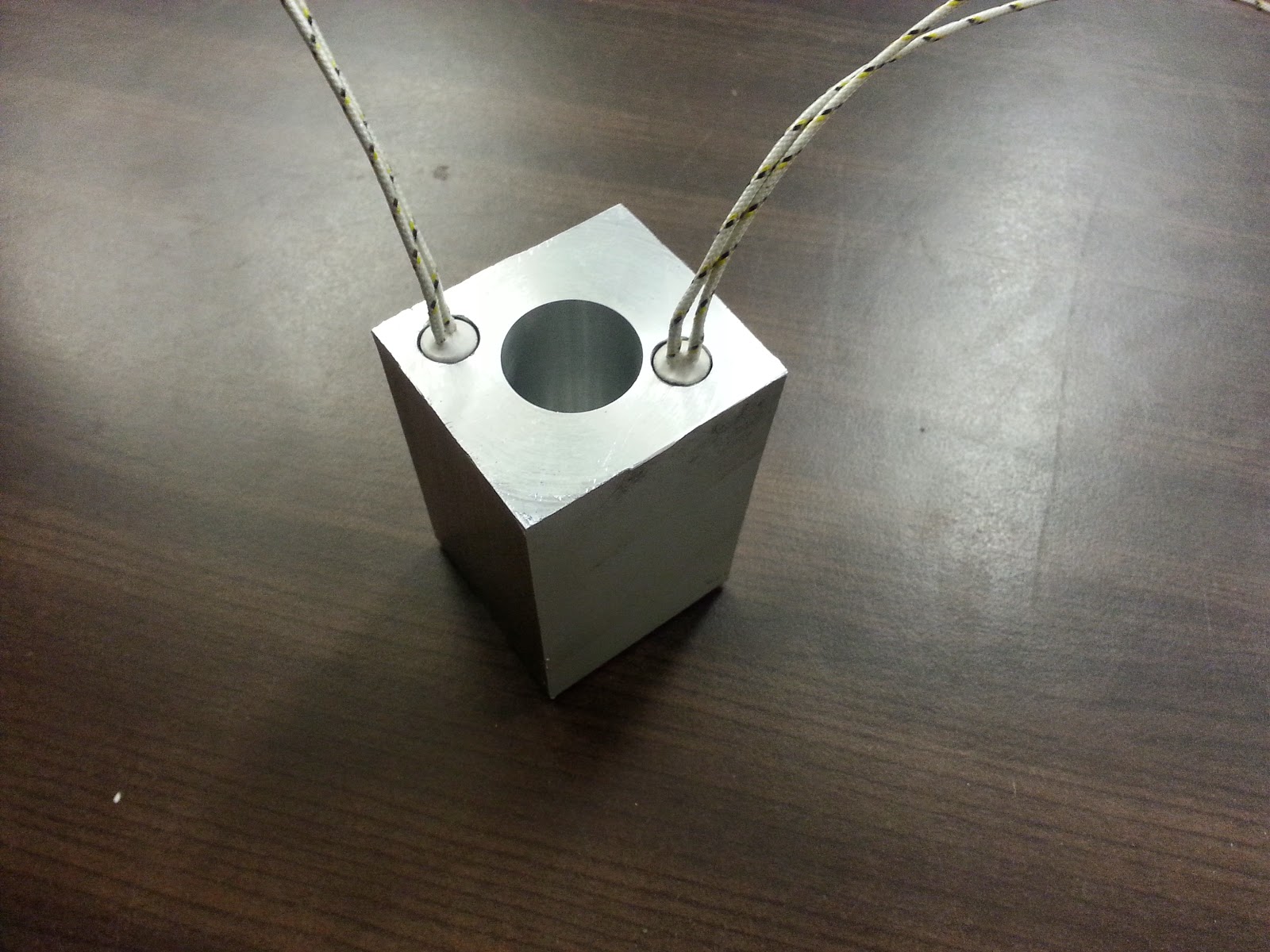
The heater chamber on the left is noticeably further away from the main chamber than the one on the right. It's just something we'll have to learn to live with for now. Note how the top of the block is not square, and how the sides taper towards a much more square base - all thanks to the wonky bandsaw!

The cartridge heaters are exactly 10mm and are an extremely tight fit into a 10mm hole. So tight (and, perhaps, because they may not have been manufactured to the most exacting of tolerances) we had to make the holes 10.5mm to get them in. Obviously an air gap between the heater and the block is undesirable, so we'll coat them liberally with some heat-sink paste to ensure a good strong contact.

The biggest job of the evening was clearing up. There was swarf everywhere! After clearing the workshop, we had to be very careful emptying the swarf from inside the main chamber.

This chamber will have moulten plastic in it, and we'll use a snug-fitting ram to push it out of a nozzle on the bottom. So we don't really want the walls of the chamber to have marks and scratches in them, or to provide any little nooks and crannies that hot plastic can settle in - as this will make the ram difficult to operate in future uses.


At the end of a long night, we ended up with a half-decent (ignoring the dodgy cutting and off-centre drilling) heating chamber. We're waiting on the thermistor now, then we can build our temperature controller.


Tuesday 27 January 2015

Designing for CNC milling for casting and injection moulding

Having got to grips (sort of) with Inkscape and gcodetools we've managed to design a few different patterns for CNC milling. Our original plan was to mill some masters to make silicone moulds (which in turn would be used to case 15mm terrain in dental plaster) so we've got some designs ready to do just that:


We've found a slightly different approach to making our CNC patterns than in earlier attempts (which we'll detail further in a future blog post) and using a bit of manual intervention, even managed to improve the paths for pocket milling. The end results in OpenSCAM look quite encouraging...


So we've got some designs to make blanks for silicone moulds. When we've got the CNC router up and running, we've already got the materials to try out, so we'll hopefully see some new rubber moulds in the next few days.

Re-drawing the patterns to leave the required shapes in relief (almost like making a negative of the final design) and manually adjusting the images in Inkscape to allow for different milling bits has meant drawing "oversized" shapes. Just out of interest, we had a play creating an "opposite" mould - one that acts like a cavity, suitable for resin casting, for example.

Drawing this type of mould required a very different approach and took some thinking about, just to get all the layers in the right order, and the different cutting depths the right way around! But after a few false starts, we managed to come up with something that looks like it might just work


This time, we had to make all our deepest  cut lines follow the inside of the shapes (rather than the outsides, as before) so that they defined the actual shapes required (whereas when making shapes for the silicone moulds, the cut lines could be as wide as we liked, so long as they were outside of the material we wanted to leave behind).

It also meant that the bits we wanted "intended" on the final piece had to be milled to stand slightly proud of the bottom of the milled pocket (rather than cut into the shape we defined). It took about 30 attempts to get this one right!


And then things went a bit crazy.
So we could make a mould that, when we fixed to a flat back, we could pour resin (or similar casting compound) into, provided we allowed a little hole somewhere, to pour it into. And then we got to thinking that perhaps, instead of a flat back, we could duplicate the pattern, to allow "proper" 3d shapes to be cast.

By adding a few locating holes, and a small channel to feed the casting compound into the mould, we could simply copy-and-paste to create a mirror image of the shape to be cast. These two halves could be placed back-to-back, to create one, single, double-sided shape!


Although the Inkscape drawings look a little sketching, with overlapping lines and multiple layers that don't quite look right, the resulting gcode looked pretty promising, in OpenSCAM.


So now we've a pattern to CNC rout a mould directly from the milling material (rather than covering a "negative blank" with silicone rubber to create the mould indirectly). Resin is an ideal substance for direct casting (it is possible to create a two-part mould with silicone rubber and use it to cast resin, but resin does cause the mould to degrade quite quickly - in anywhere between 10 and 20 casts) but already we're considering alternatives!

Resin is a relatively expensive material for casting - it's probably why most "homebrew" miniature casting set-ups use white metal (a mix of lead and pewter usually) though some companies do offer "resin masters" - at anywhere between five and ten times the price of a white metal miniature. But we've got one eye on another, far cheaper, material altogether...

Plastic injection moulding is a relatively simple process, providing you have the materials and equipment to do it. It's not as popular in homebrew/diy circles than resin, because it does require some equipment up-front. Firstly, the moulds need to be made from tough, strong, durable, heat-resistant materials, not the relatively soft, heat-damaged, short-lived silicone rubber that are suitable things like plaster and resin casting. But if we had the equipment, the actual plastic material can be very cheap indeed.

Obviously, we need to prove that we can CNC mill our sample materials - if we can mill directly from blocks of aluminium, that would be perfect. But even if not, we're already aware that there's a multitude of materials on the market, suitable for making moulds from. So if we can make the mould, we'd need some kind of injection moulding machine.

Just a few minutes on eBay and we've already ordered a couple of cartridge heaters (http://www.ebay.co.uk/itm/291048781200)


and a thermocoupler module, for controlling the temperature of the heater elements


The idea being that we've already got a hydraulic bench press over at BuildBrighton - so there's no need to recreate a frame and lever arrangement so often found in homebrew/diy injection moulding machines. We could create a heater block, into which we place plastic pellets (or recycle some PET2 drinks bottles by cutting them into strips by hand) then plunge the press onto a piston in the melting chamber, to squeeze the hot plastic out into our (aluminium, CNC milled) moulds.


The heating block could be as simple as some 2" or 2.5" square aluminium solid bar, cut to about 70mm-80mm, drilled with a couple of 10mm holes (for the heater elements) and a larger - possibly up to 30mm - hole for the melting chamber.

At the bottom of the melting chamber, we'll probably need a smaller hole (the larger one does not go all the way through the block, but stops short of the bottom of the aluminium bar) into which we'll tap a thread, so that a cone-shaped nozzle can be fitted to the bottom of the heater block. The purpose for this is twofold. Firstly, it should allow for easier cleaning of the machine (should the nozzle get blocked with hardened plaster) but, more importantly, it provides something that can easily be placed over the opening in the mould - to ensure that the plastic gets forced into the inside of the mould and doesn't simply get squirted all over the exterior!

As ever, the eBay stuff will probably take a few days to arrive, so it's unlikely to be here in time for the next BuildBrighton meeting. But in the meantime, there's no reason why we can't prepare some aluminium block and spend a bit of time trying out the CNC router. If we can't make the moulds in the first place, all this fancy talk of building an injection moulding device will be for nothing anyway!


CNC milling materials

While investigating materials for milling on the desktop CNC machine, Steve suggested medium density foam, and I found a website offering a wide range of different types of milling materials, over at http://www.johnburn.co.uk/

Having no idea what I was doing, I asked if they could recommend which material to use for making moulds for casting, and sent a link to this very blog. There is little information about the difference between all the different types of model board and foam block (and whatever else it might be called under different trade names) anywhere on the 'net, so I just emailed to ask which would be best.

After sending my home address, I got an email from Julie who said their technical rep would be in touch to discuss the requirements and in the meantime, they could send a sample of typical milling material in the post. Less than 24 hours later, and the postie dropped off a heavy little box, stuffed full of all kinds of goodies!


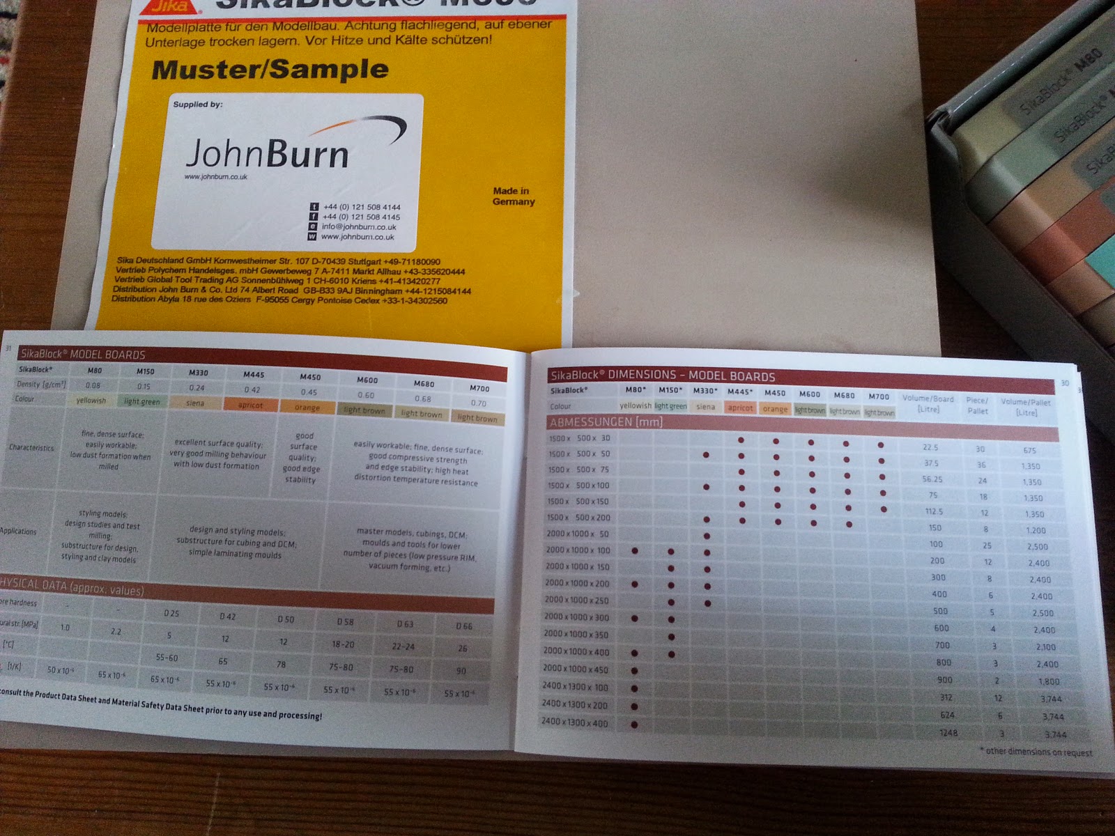
There's a great big block of heavy, dense board (it's more  a block than a board as it's about 50mm thick!) and a box full of perfectly sized sample "sheets" which are the ideal size for routing out maybe two or three 15mm wall sections on each. The box also contained a handy leaflet giving typical uses for each material type.


Some of the foam blocks look and feel like foam. The lightest material is almost as light as florists foam, but much more rigid (though you can deform it by simply pressing in your hand)


At the other end of the scale, there are also pieces of material which feel incredibly dense - not only heavy, but having a solid sound when you tap on them. They feel almost like small slabs of stone!


The lighter foam sheets have a very definite "grain" to them. It is entirely possible that even after milling, these lighter foam blocks might have a slight textured appearance. The denser blocks also have a slight wood-like grain on the surfaces, but the cut edges of the blocks give an idea of how they might appear after milling.


The little booklet also gives a table of settings for each material type. There's data for tool size, cutting depths and feed rate, amongst others. However, we're going to have to do a bit of investigating into what these mean exactly, as even the lightest foam lists the cutting depth for a 4mm bit as 0.1mm per pass and a feed-rate of 290m/min. We've no idea how this relates to a the settings we need to use for a our big, slow, desktop CNC machine, with a puny 1mm router bit.

If we could get CNCPaul to answer his emails, maybe we'd have more of an idea..........

Monday 26 January 2015

Miniature terrain casting and CNC routing

Sometimes you just have to document your failures, as well as successes. Today is one of those times - after getting back from petanque yesterday (we got through to the knockout stages, having finished in the top 16 of nearly 40 teams since you ask, but were quickly eliminated by far more experience teams!) we had a go at casting some sci-fi scenery from one of the moulds we had made over the weekend.


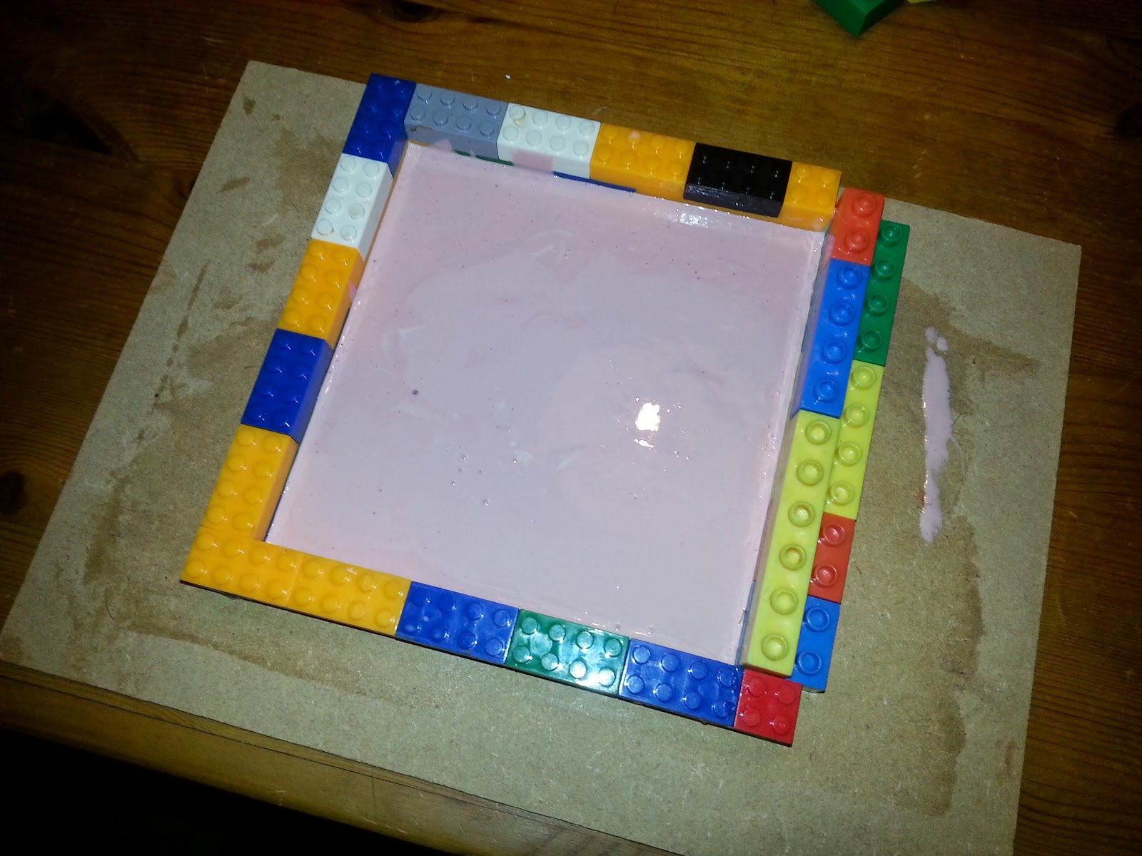
Two-part RTV (room-temperature-vulcanising) silicone rubber is great for picking out detail when making moulds. The only thing is, it may actually be too good at picking out details! Not only does the silicone show up the wood grain on some of our shapes, but it also seems to have managed to seep under the thin veneer we had glued to the mdf. You can see where this has happened especially in the top-left of the photo, where there should be a line of vertical slots in the wall - it is almost like a single, solid blob of rubber!


We made up some dental plaster, but made it a little runnier than usual (to allow it to flow into the tiny details on some of our pieces) and you can see that the mould had even picked up the join between the laminate and the mdf backing piece (the photo also showed that we made a bit of a pig's ear of the plaster too, as it's full of tiny little air bubbles!)


Our door sections also need a bit of a re-think and they are very delicate, at the thinnest part. So all in all, we've a lovely large, useless, pink rubber mould that can be used - at best - to make some pretty crappy looking sci-fi scenery! If we're going to re-do this, it needs a bit of a re-think.

Luckily, Sunday night is a great time for re-thinking ideas. One thing a laptop and an evening of boring period dramas on telly let you do, is explore a few ideas.

In the Nerd Unit we've an A3 CNC router which is woefully under-used (I think it was fired up to draw a PacMan face a number of years ago, and we used it to drill a grid of holes in some copper clad board about twelve months ago) and we've never really spent any time getting used to it.

Inspired by Iain's recent Google+ post, demonstrating some of the amazing self-designed patterns he was routing out on his own CNC machine, we thought it was time to learn how to do something more than draw pacman, or carve specialised PCB shapes with the machine we have in the unit.


It's using Mach3 software to control it - which is akin to learning to fly a space shuttle just to pop to the shops in a car. It's very complicated! Luckily, it can also import pre-built g-code and just drive the CNC machine - so that's how we're going to use it; like a glorified printer driver. All we need to do it learn how to make g-code from our drawings....

Since the drawings are in Inkscape already, it sort of made sense to download gcodetools - an Inkscape plug-in that, well, generates g-code from your drawings. That sounds ideal! There are loads of tutorials on the net explaining how to use them, so we won't go into that here. But, after just a few minutes, we had the extension installed and ready to use.
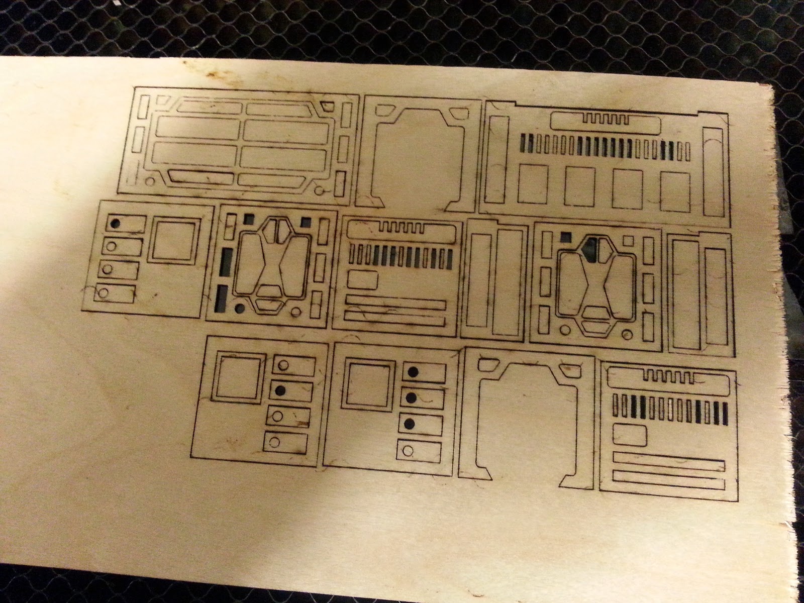
Here are some of the shapes we laser-cut in our previous attempt.


We took one of the more complex designs and prepared it for CNC routing. Because Inkscrape doesn't compensate for things like routing-bit diameter, we had to do this manually. It basically involved increasing the stroke size of the shape to be cut to 1mm, then adjusting the size of the shape (increasing if we wanted to keep the "island" bit in the middle, decreasing if we we creating a "pocket" and wanted to keep the material around the outside of the shape). Some of the shapes overlapped. That didn't really matter - it just shows that in some places, the cutting head will be moving over areas already cleared by a previous pass.


The gcodetools extension made short work of filling the "pocket" shapes with lines. In some cases, it created a lot of unnecessary lines (the fill function repeated a lot of our outline shapes for example) so a bit of manual tweaking was necessary. But it wasn't difficult to do - just a little time consuming.


Generating the G-code is as easy as selecting the function from a menu in Inkscrape. The actual image gets an additional layer, showing the cutting direction that the generated gcode will take. The extension also creates a separate .ngc file, in a folder of your choosing, on the computer.

With the gcode created, we needed a way of testing it worked. Of course, we could have just left it at that, taken the code down to the unit one evening at tried it out on the router. But that's also a really quick and easy way to use up all your router bits or even damage the cutting head - running untested gcode is always a big risk!

Thankfully, the home-CNC scene has changed quite a bit from previous years, thanks to all kinds of open-source designs, and people generally getting behind the whole open-hardware movement. One result of this is the brilliant CAM simulator, OpenSCAM.

In this case, SCAM doesn't mean it's a scam (the internet is far more subtle than that!). The S in CAM is for "simulated" - so it's software for simulating "computer aided machining". Just what we were looking for! Simply load in your pre-generated gcode and watch the cutting head path (the software can draw the the paths and has a great animation tool, to show you exactly how the shape(s) will be machined from your piece). Depending on your requirements, you may need to adjust the cutting piece Z-offset and the diameter of the cutting bit, to match the settings in your Inkscape file - otherwise your milled shape may be unrecognisable the first time you see it!


The image above shows the final piece after the milling operations have completed. The software does a great job of simulating a cutting head, and the resulting 3d shape allows you to inspect the milled piece from all angles. The gcodetools extension doesn't create optimised cutting paths - it goes with the easiest to calculate, not the best-to-run paths!


The paths shown above demonstrate that the cutting head is doing a lot of unnecessary lifting and moving across the piece, only to lift and move back to the previous place. There may be a way to address this in the extension options in the gcodetools extension. But it's not something we're going to spend too long on: if you want the best, most optimised cutting paths, it'd be better to manually place the cutting lines yourself. Which means you're going to be spending a lot of time tweaking, testing, re-tweaking and hand-carving a lot of gcode.

The way we see it, it's better to let the software do the work, and spend the extra time the CNC needs to complete the cuts (we're only really talking about a few minutes extra anyway) with a nice cup of tea and a biscuit. Let the machine do the work, so you don't have to!

With our simulated gcode looking ok, we're just waiting on some 1mm diameter router bits from ebay - and when we're next at the unit, we can give it a go on the real thing!


Saturday 24 January 2015

Laser cutting again - clear miniature bases and 15mm sci-fi terrain

It's been a long time since we last spent time in the Boiler Room Studios, but it was great to be back there this weekend. And, of course, that means... laser cutting!

We've been painting a mixture of 28mm and 15mm (and 20mm) miniatures of late, so it made sense that the first job should be a load of clear bases for our minis. These discs are cut from 3mm thick clear acrylic, and each is 25mm or 12.5mm in diameter, with a 4mm hole this time. We got a batch of 4mm magnets off ebay - both 0.5mm and 1mm thick, so this seemed like the ideal opportunity to try some out.


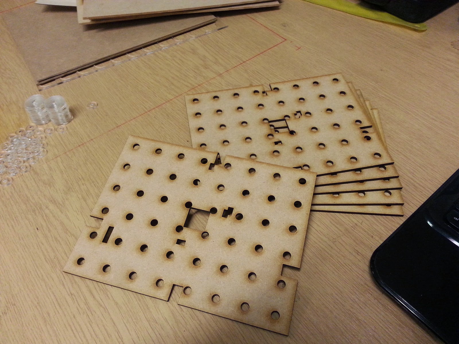
Next job was to cut some "top layers" for our board game PCBs, so we have another set of six ready to take a graphics layer. Between cutting the acrylic and cutting the mdf, we removed the air assist from the cutting head and cleaned the lens with some isopropyl alcohol.

Whether or not this made the difference, we're not sure, but our board sections ended up about 1mm too large, all the way around (they were supposed to be exactly 8" x 6") but they are ever-so-slightly larger. Then again, we're only saying that our discs are 25mm and 12.5mm in diameter - they may also be slightly over-sized (though this would be much harder to confirm, since they're tens of times smaller than the size of a board section).


Maybe it's time to do some calibration with the laser and find out if we need to scale our  images for different material thicknesses (we've used both 2mm and 3mm mdf when cutting, so perhaps it's the difference in thickness which is causing the slight discrepency?)

Sadly, we'd already cut a full set of six board pieces before thinking to measure them against an actual PCB! Never mind - a bit of manual hacking will make these work for this newest set of six, but it's definitely something to investigate, next time we're down at the studio.


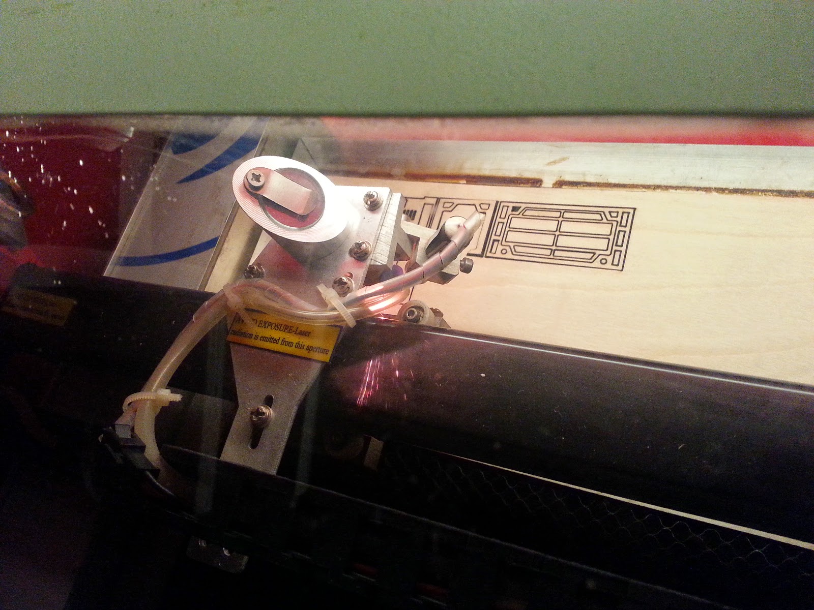
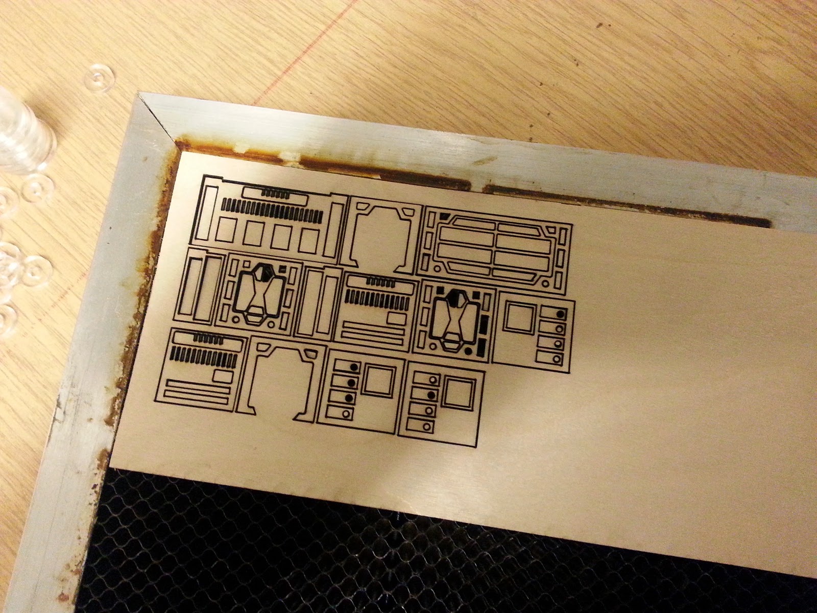
Before we'd noticed the size discrepency, we also set about cutting some 15mm sci-fi scenery. This is only going to get Grumpy Paul's blood pressure racing, but the actual shapes were designed some time ago, so it really was no extra work to dump a few ready-made images to dxf and cut them out.


The idea is to cut some walls from 2mm mdf and place some laser-cut shapes (carved from some 0.8mm birch ply) over one face, to give them a bit of detail to paint (rather than keep them all flat and use a sticker, as we did with our wild west buildings).


Coming off the laser, the cut-face appeared quite scorched. But simply putting strips of sellotape across the sheet allowed us to turn the laser-cut shapes over and see how clean and accurate the actual cutting was


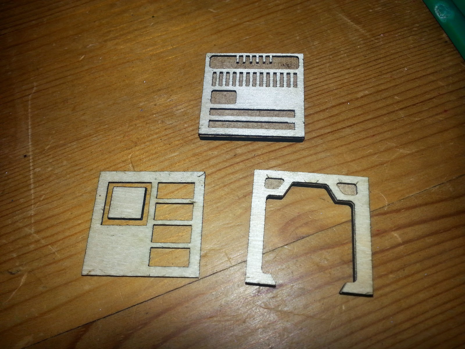
By carefully prising the shapes off the sellotape, constructing wall sections of 1" and 2" lengths was relatively straight forward. The shapes were glued to the mdf using PVA glue, which allows time to move things exactly into position (superglue would give an instant fix, but it would be very easy to end up with mis-aligned shapes if we rushed this part!)


Where shapes didn't quite line up, a very light sanding with some fine-grit paper soon got everything nice and flush.


Now laser cutting a whole load of walls and extra detail might be good fun, but it's also pretty fiddly. The walls look fine even in a wood finish, but they would look superb with a coat of paint!


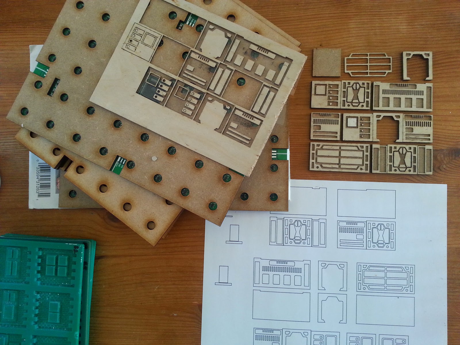
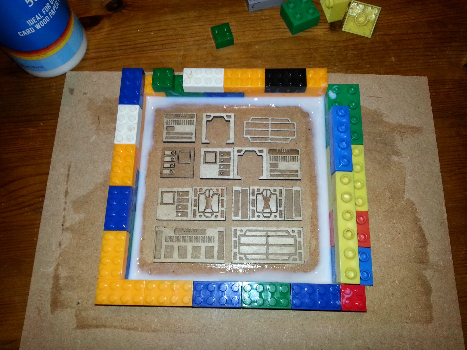
The previous photo shows where we got our next idea from - Paul's Linka moulds are great for making multiple wall sections quickly and easily. So we're going to make a mould from our wall shapes too. This means fixing the wall sections to a sheet of mdf. But before we do that, we need to seal the mdf with a coat of PVA glue (to make it easier to remove the silicone mould, once cast).


Then we gave the wall sections a wash with some 2:1 watered down PVA glue, just to seal the wooden faces, taking care not to obsure any of the finer details in the models. Then a Lego brick wall around the shapes sets up our mould framework


Rather than use modelling clay, we applied a generous bead of PVA glue between the bricks and the base, to stop the walls from leaking. Then, simply poured in the silicone and allowed to stand. While pouring the silicone into the mould, we kept on banging the table and jolting the mould, causing any air trapped inside the silicone to - hopefully - rise to the top, and capture all of the nice, fine details in the walls.


Given the number of air bubbles that came to the surface, we're giving serious thought to either sourcing, or finding someone with, a vacuum chamber. Most of these bubbles were probably introduced when we mixed the silicone with the catalyst/hardener, rather than during the pouring; there's no guarantee, but eliminating bubbles is one of the biggest problems with any kind of mould casting.

It's not only quite late now, but this silicone needs a good six hours or more to cure fully.
A few of us are off to play boules in Lancing in the morning, so this will probably get a good 18 hours or so to set, good and proper! Tomorrow we'll see how the mould turns out, and try casting a few wall sections from a bit of left-over dental plaster......

Tuesday 20 January 2015

Is 20mm the new 15mm? Why isn't it more popular?

A little while back, we got hold of some 15mm soldiers.
We discovered that painting such little miniatures required a different approach to our earlier painting techniques. Then we got some 15mm zombies. But they were way out of scale.

Our soldier miniature was enormous and chunky, and the zombies - although well sculpted and full of character, even at such a small scale - tiny and puny. It turned out that our solider was nearer 20mm and the zombies were "true" 15mm scale.

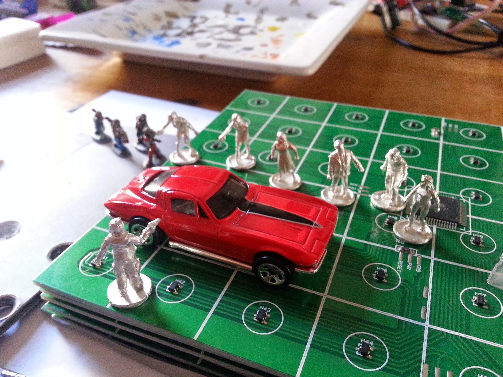
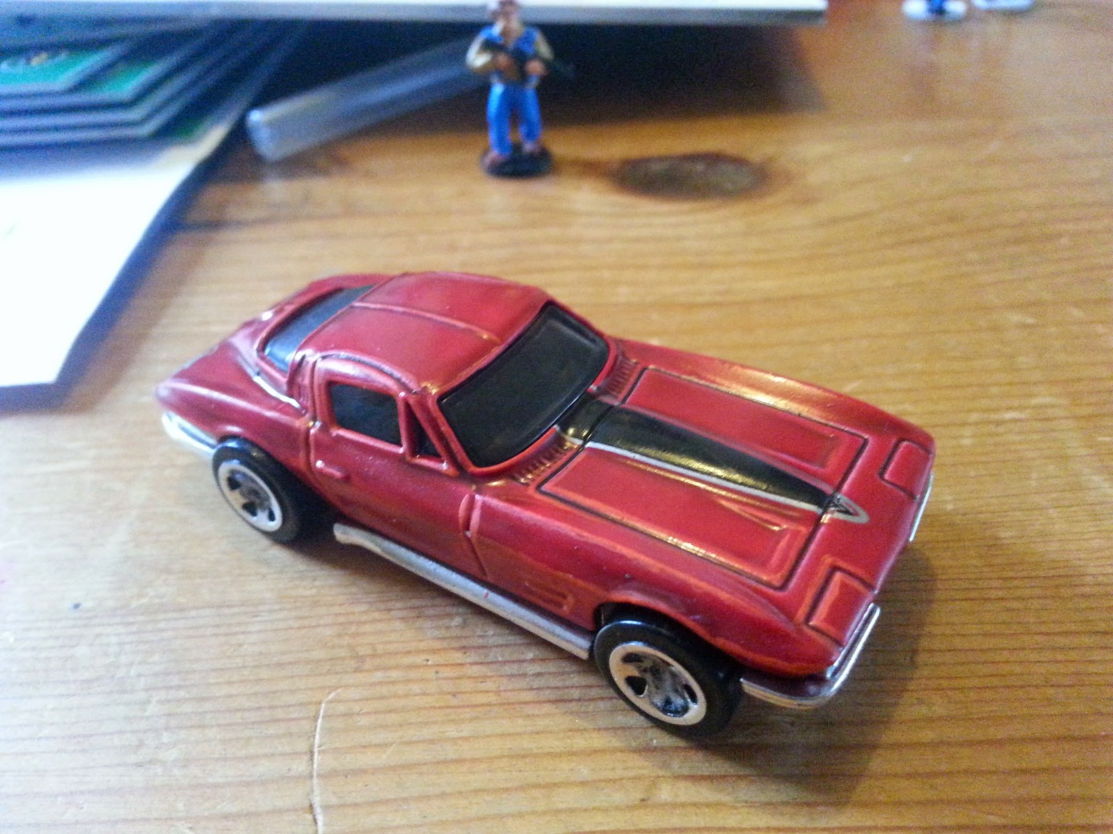
For a large horde of zombies, we figured that 15mm would be a good scale to use. Except when we came to put terrain and build a bit of interest and detail into the playing surface, things looked a little odd. Our zombieville terrain includes some outdoor scenarios, so it seemed obvious to get hold of some little cars. Die cast Corgi cars would be great. Except they look massive compared to our 15mm zombies.

Now when it somes to model-making, miniature diorama building and the like, things like scale and size start to get a bit tricky. Model makers are sticklers for scale. Tabletop wargamers tend to work with miniatures of a certain size.

Tabletop gaming miniatures used to be 25mm. The idea being that an average human character would stand at about 1.8m (1800mm) high, and at a scale of 1:72, an 1800mm high himan would be scaled down to 1800/72  = 25mm.

Then, about fifteen years or more ago, miniature painters started to demand more detail on their models. Miniatures were more commonly created at 28mm, with the argument that a model which was 25mm high to the eyeline should be about 28mm in total height.

So far so good, but in the last few years, we've started to see heroic scale miniatures - these are basically "big and chunky" 28mm miniatures - which are nearer 32mm in size (with 28mm being the height to the eyeline). Because they are a bit bigger, the models have lots of nice detail, and are a little easier to paint. And as 32mm has become the popular "heroic scale" and with the advent of super-detailed, resin-cast miniatures, 35mm is becoming the new 28mm (or the new 32mm, or the new 35mm scale... you get the idea).

Likewise, 15mm miniatures are also seeing "scale creep" - with many 15mm miniatures actually measuring anywhere between 16mm - 19mm high. Having already discovered that "true" 15mm models are too small, and 25mm miniatures are too big to use alongside street furniture, like Corgi cars, what we need is something somewhere inbetween....

As luck would have it, Elheim Miniatures do a range of 20mm gaming pieces. Their website states "All our miniatures are 1/72 scale (20mm in wargame sizes)..."

Incredibly, Elheim sell a whopping 20 zombies for just £12.
Compare that to 28mm (or 32mm heroic scale if you like) where you can easily pay between £4 and £14 per single miniature(?!) and you can see that 20mm offers great value for money.


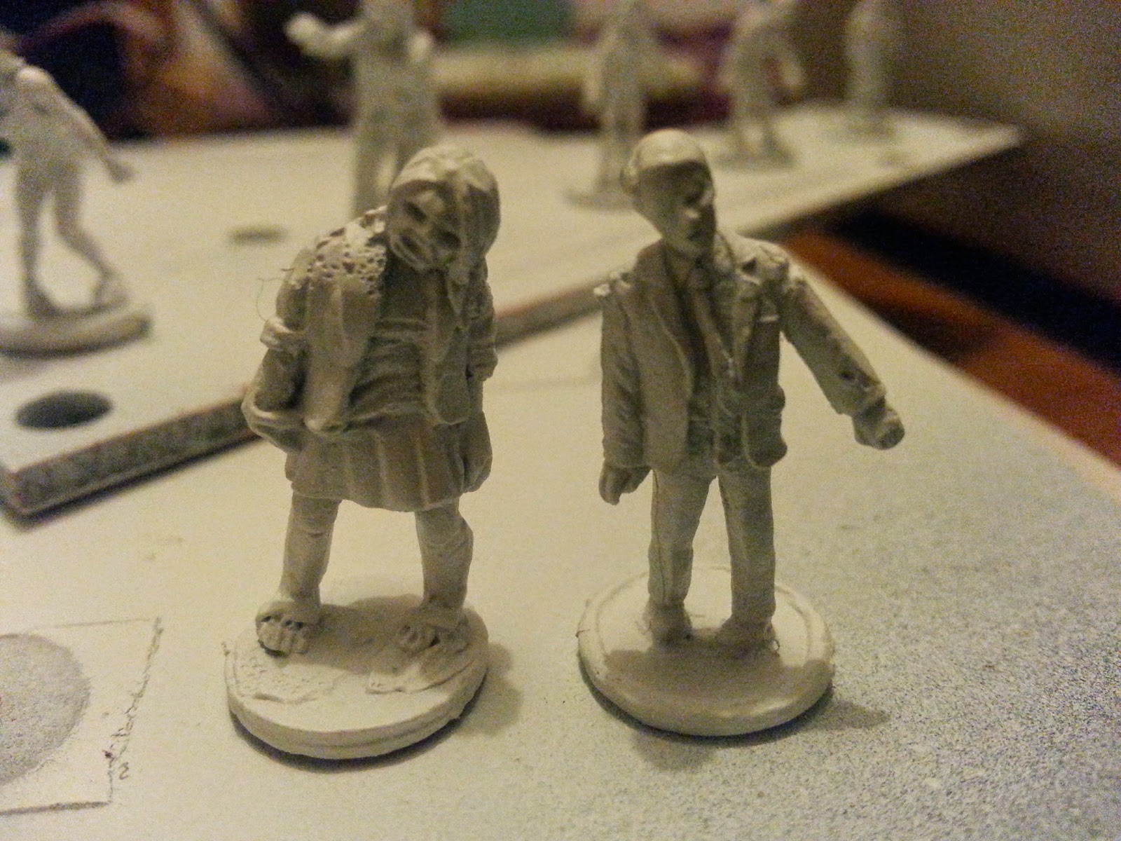
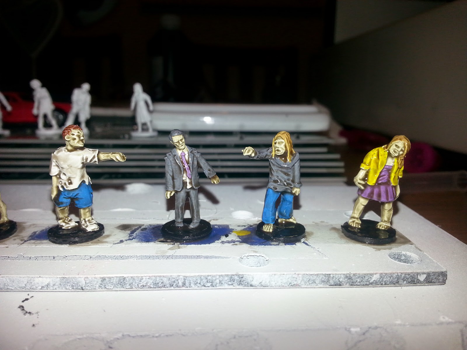
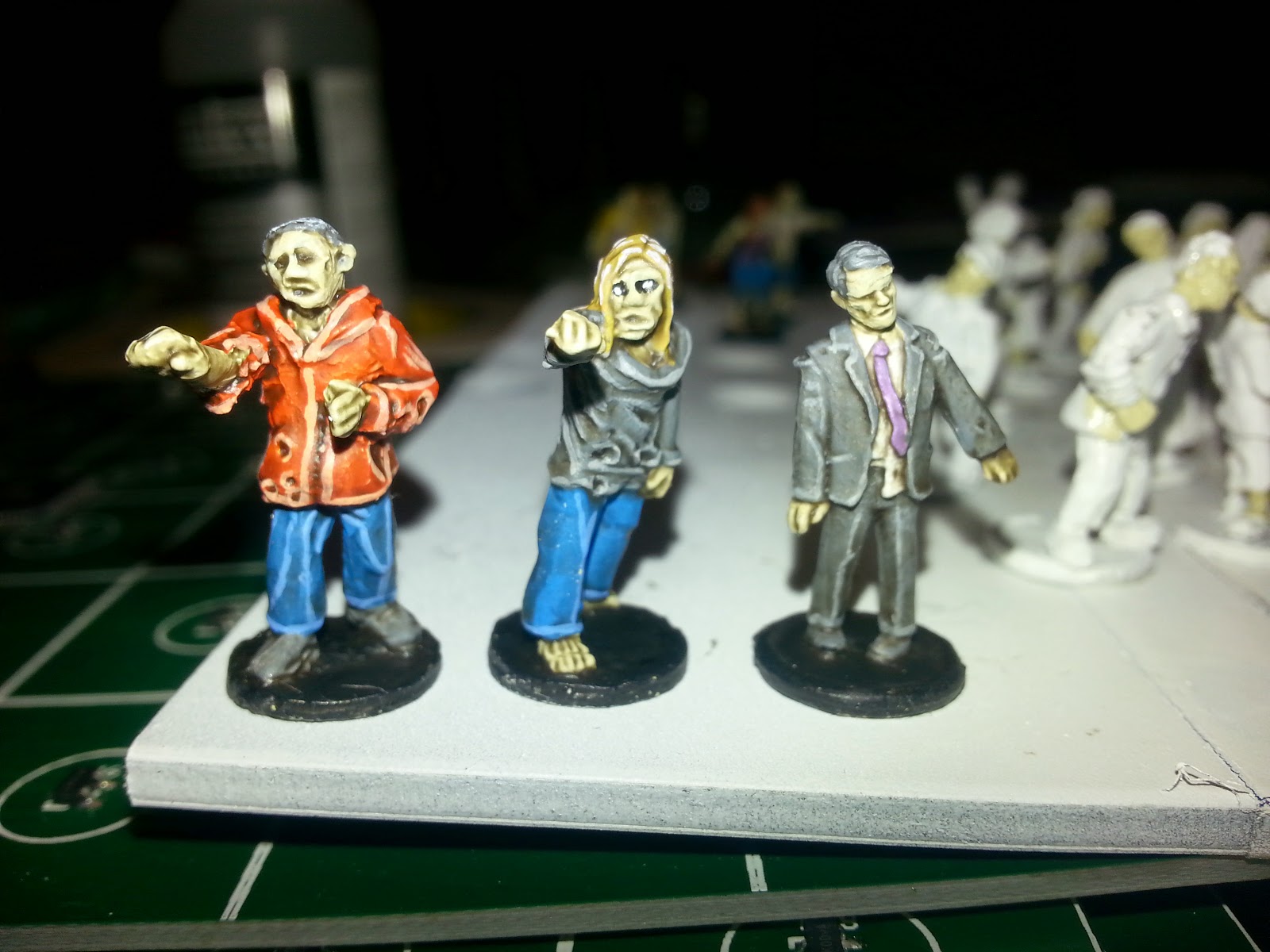
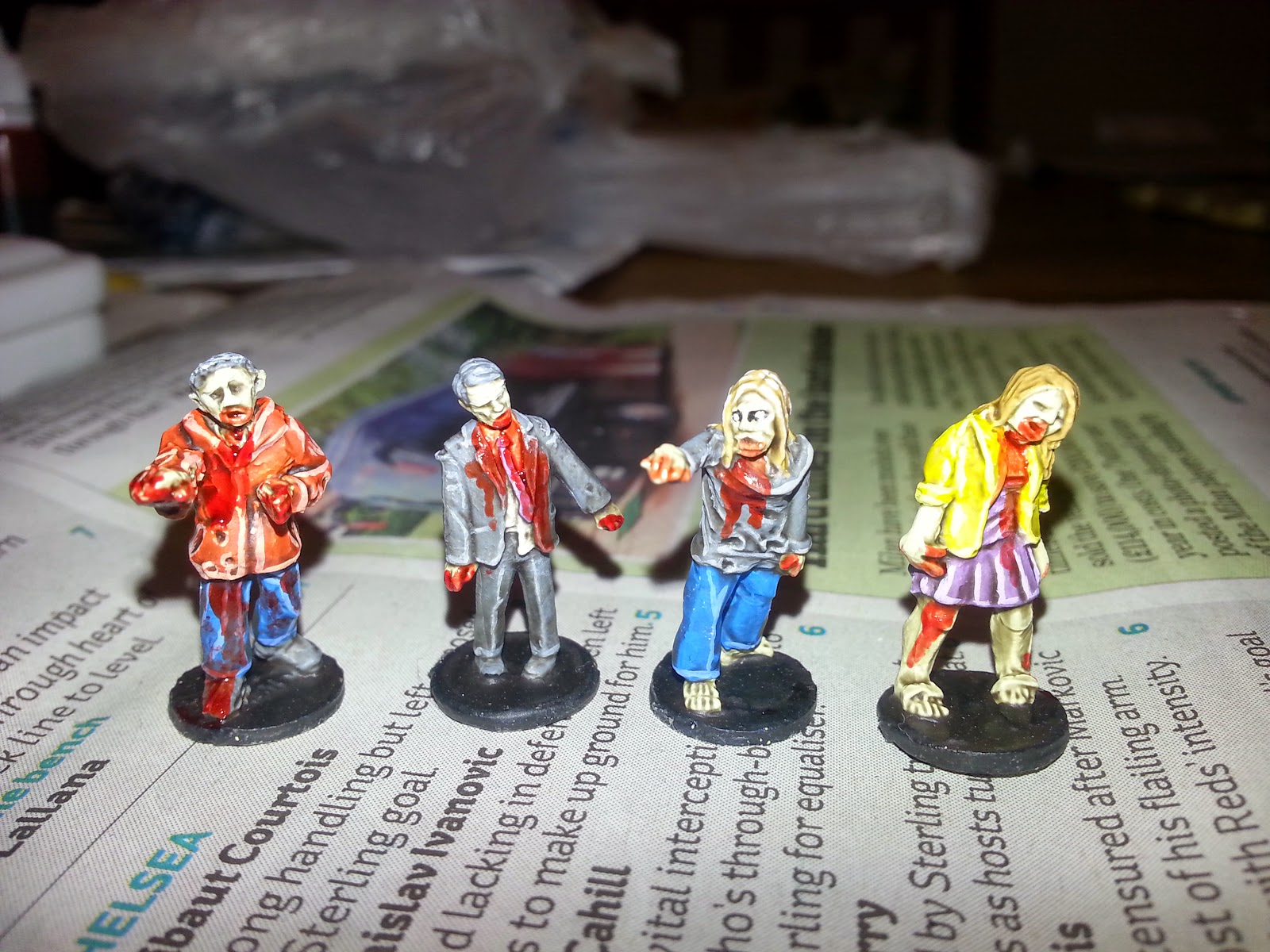
The sculpts are nice and detailed, but small enough to be quickly painted too (we eventually managed seven zombies in about two-and-a-half hours, not including Quickshade drying time).

And just as importantly - for a zombie apocalypse scenario with outdoor settings - they're just the right size for use with our terrain and street furniture. We're keen to stick to models that are easily accessible, so if anyone else wishes to play the same scenario(s), they can use easily-sourced "props" for the game (like die-cast cars from a local charity shop or supermarket, as we managed).

(included in the photo above is a Hot Wheels car, from Asda that cost just 99p)

With our scale now sorted out (seriously, why isn't 20mm more popular for tabletop gaming?) it was time to crack open the Army Painter Mega Set and see how they looked painted up. As the sculpts are a little larger and have a bit more detail than the "true" 15mm minis (though not so much as to require as much time and effort as the 28mm/32mm models) we decided to go back to our preferred painting method:

1. Prime the miniatures with white spray


2. Splash on bright base colours


3. Hit the miniature with Quickshade Dark Tone (we used Dark rather than Strong Tone to create a higher contrast between the edges and crevasses in the sculpt - these miniatures are still quite small, so a high-contrast approach works well)


4. After drying, coat with Dullcote to take the shine away, and add some very simple edge highlights. There is no need to spend a great deal of time on this stage, but picking out the odd highlight can really make the difference when the model is viewed from arm's length on the tabletop.

(once again, the flash on the camera makes the edge highlights on these models look much more severe than they are in real life - though we did use quite high contrasting colours)

5. Mix up some Tamiya Clear Red and black in and splosh on the gore!


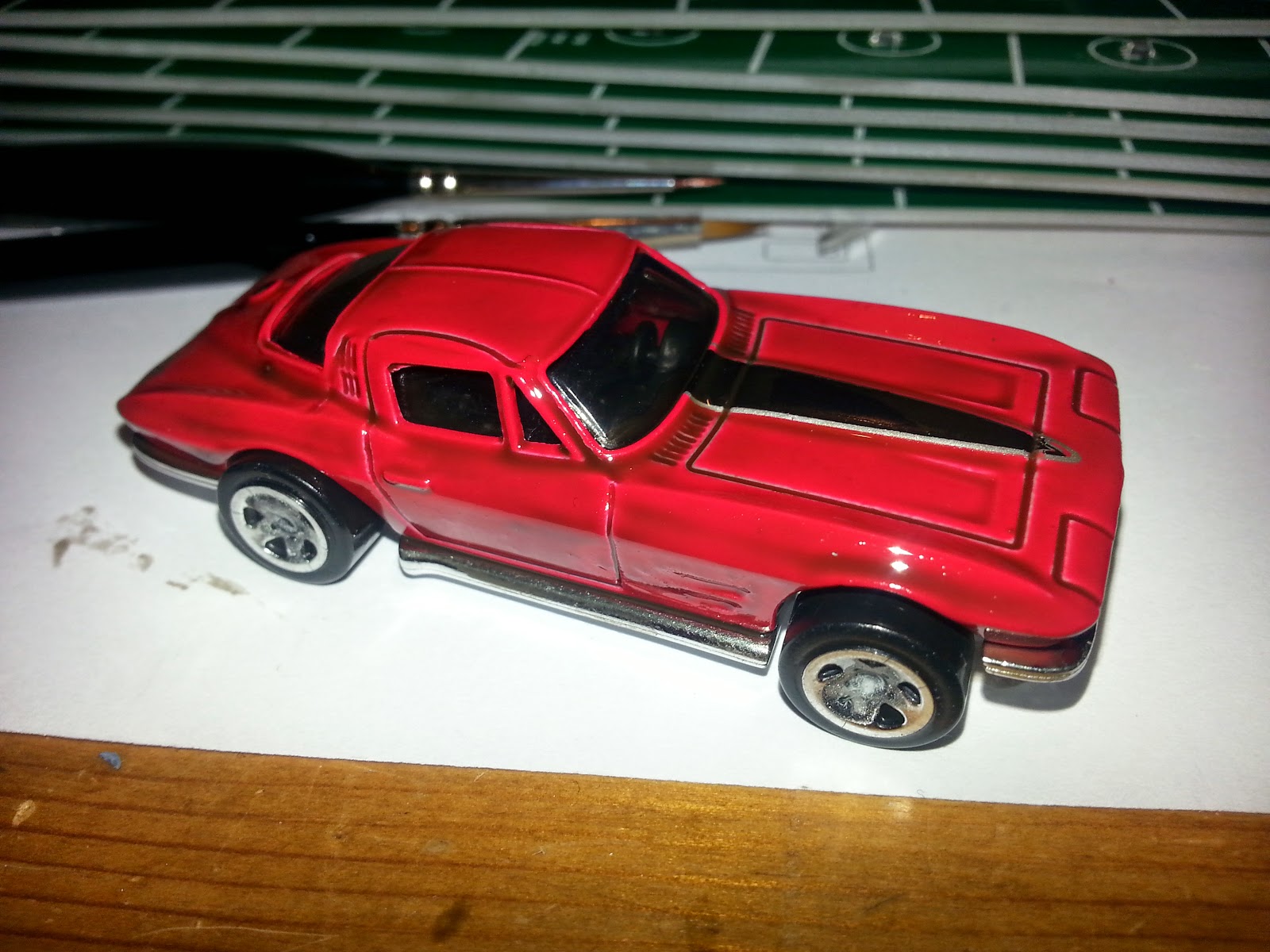
For our cars, we simply coated the original vehicle, straight from the packet, in Quickshade Dark Tone. We applied the tone quite liberally to help reduce the effect of any brushstrokes, but took care to avoid "pooling" where possible.


This time we left the car, without applying Dullcote, to keep the slightly shiny effect (after drying, the Dark Tone wasn't quite as shiny as we expected). This is because most modern cars are finished with a metallic (rather than purely matt) paint, so the slight sheen simulated the car paint finish quite well. The Dark Tone picks out all the edges and door outlines and so on quite nicely.


Maybe we went a step too far this time - the orange edge highlighting just didn't quite work on this one. Maybe it was the choice of colours, or maybe it was just an effect that isn't suitable for this kind of model. But in future we're going to just stick to Dark Tone and call it done!

We think that the 20mm zombies (and survior) models look great on the tabletop alongside the easily-sourced die-cast cars. There's a whole raft of easily-found street furniture and terrain building materials available in 1:72 (and, if you really need it 1:76) scale and even model railway 00 scale. And it all fits in quite nicely with our 20mm miniatures.

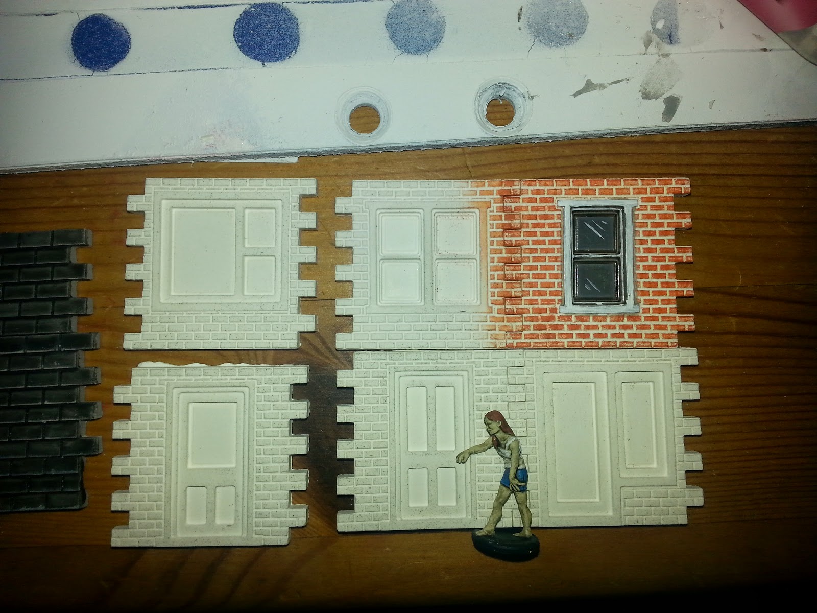
Grumpy Paul even suggested using some old "Linka" moulds to make terrain and buildings for this new scale. Although not exactly a perfect match for our 1" square grid (a four-section terrace takes up almost 5" on the board), a short terrace of houses can be quickly and easily made up by casting just a few pieces, and they don't look too small or out-of-scale for the miniatures:


(painting the brickwork on these models was quite quick - mix up a red/brown paint and dry-brush directly onto the bare plaster; the white appears as the mortar between the bricks. If necessary, a quick sepia wash can tone the shade whole model down, but - since our zombies are so cartoon-y - we quite like the bright-and-clean look, for now)

20mm miniatures are almost as cheap, per unit, as 15mm miniatures (whereas 28mm are comparatively expensive) and terrain is cheap and easily found in a range of styles. Which begs the question - why isn't 20mm more popular for tabletop gaming??